


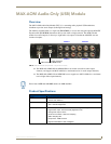
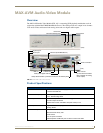

MAX-AVM Audio-Video Module
12
MAX AOM and AVM Modules
Installing the MAX-AVM
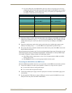
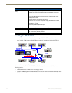
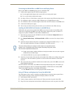
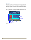
MMS servers communicate via Ethernet to up to 25 MAX-AVM audio/video modules.
Multiple AVMs require a Gigabit Ethernet switch (not included) as indicated in FIG. 11.
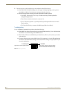
The procedure for installing the MAX-AVM is outlined below, and the steps are described in the
following sections:
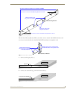
1. Connect the AVM to an MMS server and a display device.
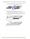
2. Install the AVM Setup Serial Number (indicated on a decal on the bottom panel of the AVM) in the
MMS server.
MAX-AVM (FG 2178-50) Specifications (Cont.)
Rear Panel Connectors
(Cont.):
• RS-232 port: 9-pin (DB-9) Serial port.
• Ethernet port: RJ-45 Ethernet port provides 10/100 network connectivity
between the AVM and the MMS server.
• USB ports: not used.
• S-Video Out: Mini-Din4 port provides composite S-video monitor output.
• Parallel port: not used.
• VGA out: DB15HD port provides VGA output.
• Audio Line Out: 1/8” stereo analog audio output (for use with the included
RCA Y-adapter).
• Line In/Mic In: not used.
• RCA (coax): S/PDIF digital audio output.
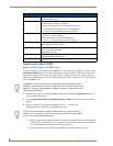
Dimensions (HWD): 2 3/16” x 7” x 11” (5.56 cm x 17.78 cm x 27.94 cm)
Weight: 6.50lbs (2.95 kg)
Included Accessories: • 12VDC 5A external power supply
• 1/8” stereo to RCA (female) Y adapter
Certification: FCC, CE
FIG. 11
Example installation using multiple MAX-AVMs
MMS-12S Server
MAX-AVM
MAX-AVM
MAX-AVM
MAX-AVM
MAX-AVM
A/V OUT (GB)
10/100
MAX-AVM
MAX-AVM
MAX-AVM
10/100
10/100
10/100
10/100
10/100
10/100
10/100
Gigabit
Ethernet
Switch
ETHERNET
CONTROL (GB)