


For full warranty information, refer to the AMX Instruction Manual(s) associated with your Product(s).
1/09
©2009 AMX. All rights reserved. AMX and the AMX logo are registered trademarks of AMX.
AMX reserves the right to alter specifications without notice at any time.
3000 RESEARCH DRIVE, RICHARDSON, TX 75082 • 800.222.0193 • fax 469.624.7153 • technical support 800.932.6993 • www.amx.com
93-2105-06
REV: F
1. Discharge the static electricity from your body by touching a grounded metal
object and unplug all the connectors from the unit.
2. Remove the three screws by turning them in a counter-clockwise direction and
remove the front faceplate.
3. Align the edges of the card with the internal guide slots and gently slide it in all
the way until the rear edge of the card snap into place.
4. Re-secure the faceplate by inserting the three screws by turning them in a
clockwise direction and securing the front faceplate to the Controller.
5. Re-apply power and other connections as necessary.
Setting the Integrated Controllers’ starting Card Address
The rear 8-position CardFrame Number DIP switch, lower-left rear of the Integrated
Controller, sets the starting address (the device number in the D:P:S specification)
for the Control Cards installed in the controller.
The Control Card address range is 1 - 3064.
The factory default CardFrame DIP switch value = 0 (All CardFrame DIP
switches in the OFF position).
The formula for setting the starting address is:
(DIP switch value) + Card slot Number (1 - 4) = Card Address
For example:
A DIP switch setting of 00010101:
(0 + 0 + 0 + 96 + 0 + 384 + 1536) + SLOT #(ex:1) = 2017.
A card in slot number 1 = device address 2017.
Set the CardFrame Number DIP switch value is based on the table below.
Cycle power to the unit for approximately 5 seconds. This allows the unit to read the
new device number settings.
Wiring a power connection
Use a 12 VDC-compliant power supply to provide power to the Controller via the rear
2-pin 3.5 mm mini-Phoenix connector. Use the power requirements information listed
in the Specifications table to determine the power draw.
The incoming PWR and GND cable from the PSN power supply must be connected
to their corresponding locations within the PWR connector.
• This unit should only have one source of incoming power.
• Using more than one source of power to the Controller can result in damage to
the internal components and a possible burn out.
• Apply power to the unit only after installation is complete.
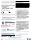
RS-232/422/485 wiring connector information
FIG. 3 shows the pinout and wiring specification information for the rear RS-232/RS-
422/RS-485 (DB9) Device Ports. These ports support most standard serial mouse
control devices and RS-232 communication protocols for PC data transmission.
The NI-4100 uses Ports 1 - 7.
WARNING: When wiring the 422/485 connections, do NOT use pre-made 9-wire
cable or connect the wire in the cable to any connection that will not be used by the
DB9 serial port. Only use wiring that connects the needed pins.
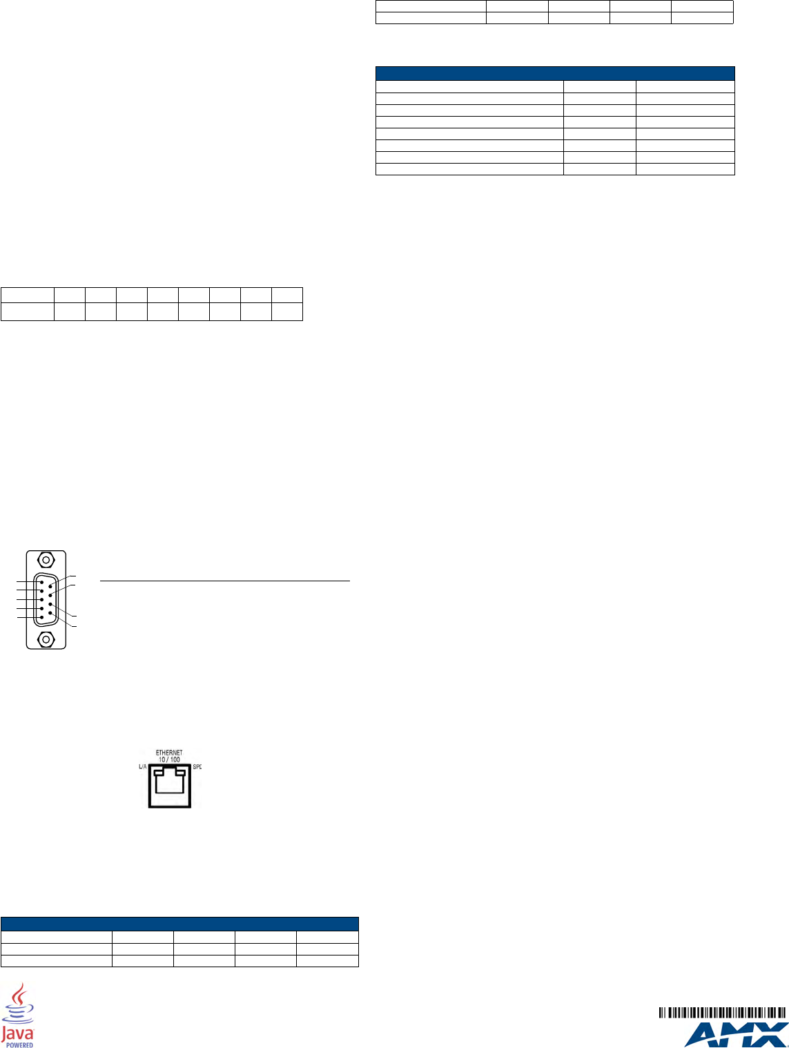
Ethernet 10/100 Base-T Connector
The RJ-45 Ethernet connector provides 10/100 network connectivity between the
panel and the NetLinx Master (FIG. 4).
Use a standard CAT5 Ethernet cable to provide communication between the
Integrated Controller and external NetLinx devices.
Baud Rate Settings (Program Port DIP Switch)
The Program Port DIP switch is located on the rear of the device. Use this DIP switch
to set the baud rate for the Program Port, according to the settings shown in the
following table. Make sure the baud rate you set matches the baud rate on your PC's
NetLinx COM Settings before programming the unit.
Note: DIP switch 1 activates/deactivates the Program Run Disable Mode. DIP
Switches 2,3, and 4 must remain OFF at all times.
Ethernet Ports Used by the NI-4100
Preparing the NI-4100 for Serial Communication
To establish serial communication with the Controller via the PROGRAM (DB9) port:
1. Use a Serial DB9 cable (i.e. CC-COM Programming Port Cable - not included)
to connect the Controller’s Program port to a DB9 port on a PC.
2. Launch NetLinx Studio 2.x (default location is Start > Programs >
AMX Control Disc > NetLinx Studio 2 > NetLinx Studio 2).
3. Select Settings > Master Communication Settings, from the menu bar, to
open the Master Communication Settings dialog box.
4. Click the Communications Settings button to open the Communications
Settings dialog.
5. Click the NetLinx Master radio button (from the Platform Selection section) to
indicate you are working with a NetLinx Master.
6. Click the Serial radio button (from the Transport Connection Option section) to
indicate you are connecting to the Master via a COM port.
7. Click the Edit Settings button (on the Communications Settings dialog) to
open the Serial Settings dialog and set the COM port parameters (used to
communicate to the NetLinx Master).
8. Click OK to close all dialogs and return to the main application.
9. Right-click the Online Tree tab entry and select Refresh System: the
Controller should appear in the Device Tree. If not, verify that the Serial cable
is connected properly, and that the Baud Rate settings on the Controller (set
via the Program Port DIP Switch) match the settings in NetLinx Studio.
Once Serial communication has been established, use NetLinx Studio to configure
the Controller for Ethernet Communication, as described below.
Configuring the NI-4100 for Ethernet Communication
Before continuing, complete the COM port steps above.
1. Use an Ethernet cable to connect the Controller to the LAN to which the PC
running NetLinx Studio is connected.
Note: The NI-x100 Controllers feature an Auto MDI/MDI-X Ethernet port. This
provides the option of using either a standard (straight through), or a crossover
Ethernet cable to communicate with a PC - both cable types will work.
2. Select Diagnostics > Network Address from the menu bar and enter the
System, Device (0 for a Master), and Host Name information.
3. To configure the Address:
• Use a DHCP Address by selecting the Use DHCP radio button, then click the
GET IP button (to obtain a DHCP Address from the DHCP Server), click the
SET IP Information button (to retain the new address), and then finish the pro-
cess by clicking the Reboot Master > OK buttons.
• Use a Static IP Address by selecting the Specify IP Address radio button,
enter the IP parameters into the available fields, then click the SET IP
Information button (to retain the pre-reserved IP Address to the Master), and
then click the Reboot Master > OK buttons to finish the process.
4. Repeat steps 1 - 5 from the previous section, but rather than selecting the
Serial option, choose TCP/IP and edit the settings to match the IP Address you
are using (Static or IP).
5. Click on the Authentication Required radio box (if the Master is secured) and
press the User Name and Password button to enter a valid username and
password being used by the secured Master.
6. Click the OK to close all dialogs and return to the main application.
Onboard WebConsole
NetLinx Masters have a built-in WebConsole that allows you to make various
configuration settings via a web browser on any PC that has access to the Master.
The webconsole consists of a series of web pages that are collectively called the
"Master Configuration Manager".
Accessing the WebConsole
From any PC that has access to the LAN that the target Master resides on:
1. Open a web browser and type the IP Address of the target Master in the
Address Bar.
2. Press Enter to access WebConsole for that Master. The initial view is the
WebControl page.
Additional Documentation
Additional Documentation for the N1-4100 is available at www.amx.com.
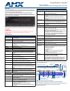
Position
12345678
ON position
Value
12 24 48 96 192 384 768 1536
FIG. 3 RS-232/422/485 DB9 (male) connector pinouts
FIG. 4 Layout of Ethernet LEDs
Baud Rate Settings
Baud Rate Position 5 Position 6 Position 7 Position 8
• 9600 bps OFF ON OFF ON
• 38,400 bps (default) OFF ON ON ON
5
4
3
2
1
9
8
7
6
DB9 Serial Port pinouts (male connector)
Pin 2: RX signal
Pin 3: TX signal
PIN 5: GND
Pin 7: RTS
Pin 8: CTS
RS-232
Pin 1: RX -
Pin 4: TX +
PIN 5: GND
Pin 6: RX +
Pin 9: TX -
RS-422
Pin 1: A (strap to 9)
Pin 4: B (strap to 6)
PIN 5: GND
Pin 6: B (strap to 4)
Pin 9: A (strap to 1)
RS-485
SPD - Speed LED lights (yellow)
100 Mbps and turns Off when the
speed is 10 Mbps.
when the connection speed is
L/A - Link/Activity LED lights
(green) when the Ethernet
cables are connected and
terminated correctly.
• 57,600 bps ON OFF OFF OFF
• 115,200 bps ON ON ON ON
Ethernet Ports Used
Port type Port # Type
• FTP 21/20 TCP
• SSH (only SSH v2 is supported)22 TCP
•Telnet 23 TCP
• HTTP 80 TCP
• HTTPS/SSL 443 TCP
• ICSP 1319 UDP/TCP
• integration! Solutions 10500 TCP