


AMX Corporation reserves the right to alter specifications without notice at any time.
For full warranty information, refer to the AMX Instruction Manual(s) associated with your Product(s).
036-004-2870 4/05 ©2005
AMX Corporation. All rights reserved. The AMX logo is a trademark of AMX Corporation. AMX reserves the right to alter specifications without notice at any time.
3000 RESEARCH DRIVE, RICHARDSON, TX 75082 • 800.222.0193 • fax 469.624.7153 • technical support 800.932.6993 • www.amx.com
93-2259-10
REV: A
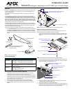
7. Assemble the Kensington Lock/Security Cable (not included). Refer to the doc-
umentation provided by the lock manufacturer for details.
8. Open the Lock to rotate the lock mechanism so that it can be inserted into the
slot on the top center of the Raised Lock Bracket (FIG. 6).
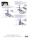
Method B: Installing the Flat Lock Bracket
1. If you removed the connectors previously, re-insert them into their proper loca-
tions on the touch panel. This ensures that the Flat Bracket will not obstructing
any of the connectors on the rear panel.
2. Align the openings on the bottom of the Flat Lock Bracket to the securing
locations on the left side of the touch panel connector plate (located under the
connector plate cover, as indicated in FIG. 7).
3. Insert two Keyed-Lock Securing Screws into their respective locations (FIG. 7).
4. Use the AMX Keyed-Lock screwdriver adapter to tighten the screws and
secure the Flat Lock Bracket to the base plate (FIG. 7).
5. Assemble the Kensington Lock/Security Cable (not included). Refer to the doc-
umentation provided by the lock manufacturer for details.
6. Open the Lock to rotate the lock mechanism so that it can be inserted into the
opening in the top of the Flat Lock Bracket (FIG. 8).
FIG. 5 Thread a tie-wrap through the center holes on the Raised Lock Bracket
FIG. 6 Lock mechanism and insertion location
Incoming cables
Lock insertion slot
Kensington Lock/Security
Cable assembly
(not included)
Security key
(not included)
Raised Lock Bracket
FIG. 7 Flat Lock Bracket - Components and Installation
FIG. 8 Lock mechanism and insertion point
Flat Lock Bracket
Kensington Lock/Security
Keyed-Lock Securing Screws (2)
Security key
Connector plate cover
Cable assembly
(not included)
(not included)
Base
AMX Keyed-Lock screwdriver adapter
Base Plate
Lock mechanism
Lock insertion point
Security key
(not included)
Kensington Lock/Security Cable
assembly (not included)
Flat Lock Bracket