


AMX Corporation reserves the right to alter specifications without notice at any time.
For full warranty information, refer to the AMX Instruction Manual(s) associated with your Product(s).
043-004-2729 05/03 ©2003
AMX Corporation. All rights reserved. The AMX logo is a trademark of AMX Corporation. AMX reserves the right to alter specifications without notice at any time.
3000 RESEARCH DRIVE, RICHARDSON, TX 75082 • 800.222.0193 • fax 469.624.7153 • technical support 800.932.6993 • www.amx.com
9
3-0606-80
REV: A
Jumper Information
Jumpers provide user-selectable configuration options on the Radia
Energy Management Modules.
The following table describes the jumper settings for various delays and
strapping:
Visual Status Indicators/Manual Override
Each relay includes a green lever that serves as both a status indicator
and manual override switch. With the lever to the left (towards the wire
terminals) the relay is in the OFF position. With the lever to the right the
relay is in the ON position.
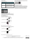
Connecting the RDM-3EM/6EM
Connect pins 1, 3 and 4 on the “A” connector only:
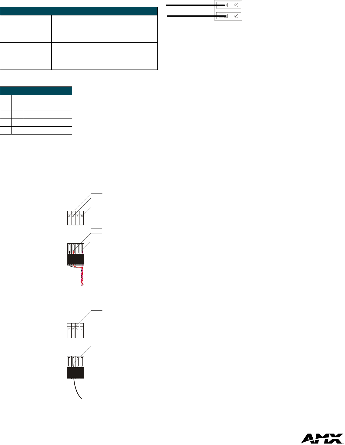
Connect only pin 3 on the remaining connectors ( “B” through “F”):
Connect the LINE IN and LOAD wiring on the (orange) 2-pin Channel
connectors, as shown below:
AMX Lighting Warranty Information
AMX Lighting products are guaranteed to switch on and off any load that
is properly connected to our lighting products, as long as the AMX Lighting
products are under warranty. AMX Corporation does guarantee the control
of dimmable loads that are properly connected to our lighting products.
The dimming performance or quality cannot be guaranteed due to the
random combinations of dimmers, lamps and ballasts or transformers.
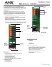
Jumper Information
Sequencing Delay
Jumpers (JP1 and JP2)
The sequencing delay jumpers are set to short (0.5
sec.) delay by default. Installers can also select set-
tings of no delay, medium delay (1.0 sec.) and long
delay (1.5 sec.) between relays to minimize inrush
current and stress on the electrical system.
Control Port Strapping
Jumpers (JP3 - JP7)
Each relay is set to an individual Radia port by default.
Installers have the option of setting multiple relays to an
individual Radia port for large area control.
For example, to combine A and B set JP3 to the ON
position.
JP1 - JP2 Jumper Settings
JP1 JP2 Delay
off off no delay
off on short delay (0.5 sec.)
on off long delay (1.5 sec.)
on on medium delay (1.0 sec.)
FIG. 3 RDM-3EM/6EM wiring connections - Connector “A” only
FIG. 4 RDM-3EM/6EM wiring connections - Connectors “B” through “F”
Pin 4 (GND)
Pin 3 (RLY)
Pin 1 (+12V)
Pin 4 (GND)
Pin 3 (RLY)
Pin 1 (+12V)
RDM-3EM/6EM 4-pin connector
4-pin connector from Radia Master
Pin 3 (RLY)
Pin 3 (RLY)
RDM-3EM/6EM 4-pin connector
4-pin connector from Radia Master
FIG. 5 2-pin Channel connectors
LINE
LOAD