


For full warranty information, refer to the AMX Instruction Manual(s) associated with your Product(s).
8/07
©2007 AMX. All rights reserved. AMX and the AMX logo are registered trademarks of AMX.
AMX reserves the right to alter specifications without notice at any time.
3000 RESEARCH DRIVE, RICHARDSON, TX 75082 • 800.222.0193 • fax 469.624.7153 • technical support 800.932.6993 • www.amx.com
93-0706-01 REV: C
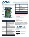
Low-Voltage Connections
The low-voltage area in the AMX Lighting controllers contain connections and DIP
switches for AXLink, dry closures, and RDM module connectors. On the controller
cards, low-voltage power for the board is supplied either by line power, optional
auxiliary power supply (RDA-PSM), or the +12 VDC pin on the AXLink connector.
WARNING: Disconnect the main power to the AMX Lighting controller at the
breaker box if rewiring the low voltage connections.
Dry Closure Connections
Dry contact closures from other equipment can be connected to the Radia Eclipse
dimmer module to provide direct manual control of lighting loads (FIG. 5).
Each dry contact closure has two pins: ground and contact. To activate each dry
closure, connect the ground and contact.
Setting AXLink Address Numbers
Set the AXLink address number (1-255) for the RE-DM4. This number must match
the device number in your Axcess program.
Note: By turning all switches off, all circuits will go to 100 percent so that the installer
can test the high-voltage connections without having connections to a control
system.
Connecting AXLink
Connect the 4-pin captive-wire AXLink from the RE-DM4 to the Central Controller for
AXLink control of the dimming system.
RE-DM4 4-pin module connector (male)
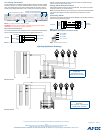
Lighting Application Drawings
FIG. 4 Low-voltage connections and DIP switches
FIG. 5 Dry Closure Connections
AXLink address DIP switch
Module connector/LED (CH6)
Dry contact closures
Auxiliary power IN
Module connector/LED (CH5)
AXlink connector
RE-DM4
FAILSAFE
GND
EMERGENCY
GND
Failsafe switch
Alarm system
FIG. 6 Connecting AXlink
FIG. 7 RE-DM4 module connector
Central
RE-DM4
Controller
PWR
AXP
AXM
GND
PWR
AXP
AXM
GND
Pin 4 (GND)
Pin 3 (RLY)
Pin 2 (DIM)
Pin 1 (+12 V)
FIG. 8 Example A
FIG. 9 Example B
Example A
Single input
Single-phase, four load
120 or 240 VAC 1
Ø
Example B
Dual Input
Single-phase, four load
120, 120/240, or 240 VAC 1
Ø