


5
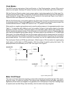
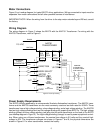
Wiring Diagram
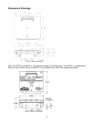
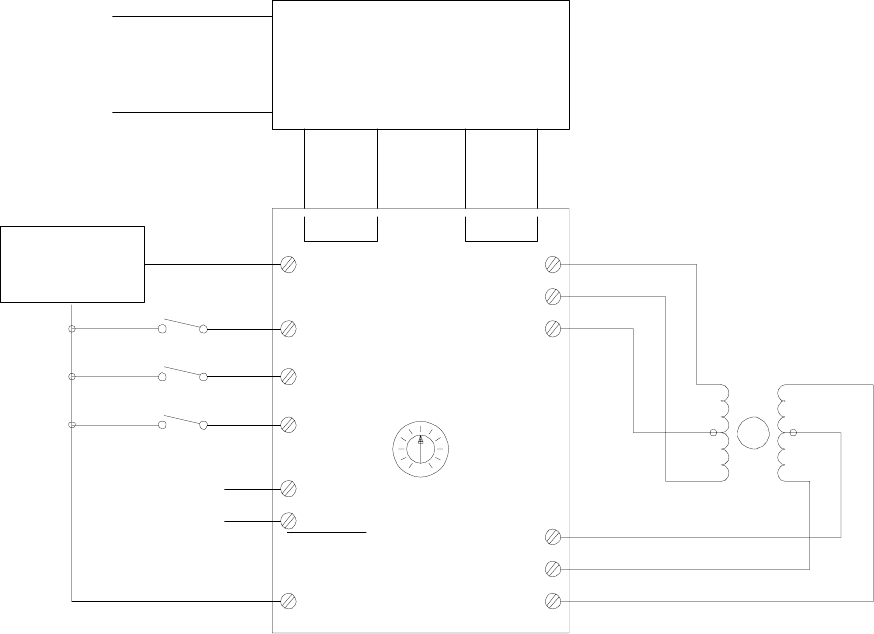
The wiring diagram in Figure 5 shows the BLD72 with the AA2791 Transformer. For wiring with the
AA2793 Transformer, refer to Figure 9.
Motor Connections
Figure 5 is a hookup diagram for typical BLD72 driver applications.
Wiring connected to inputs must be
separated from motor connections and all other possible sources of interference.
IMPORTANT NOTE: When the wiring from the driver to the step motor extends beyond 25 feet, consult
the factory.
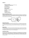
Power Supply Requirements
The BLD72 must be powered by a recommended Anaheim Automation transformer. The AA2791 trans-
former and the AA2793 transformer are the most commonly used and are both rated for 300VA. These
transformers have a high voltage winding, a low voltage winding, and a logic voltage winding. The AA2793
has two high voltage windings and two low voltage windings for powering two BLD72’s. The high voltage
winding (yellow) and low voltage winding (red) plug into the quick disconnects on the back of the BLD72
(see hookup diagram in Figure 5). The logic voltage winding (orange) is used to power up optional control-
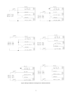
lers. When using one of these transformers, the nominal low-voltage is 5.0 volts and the nominal high-
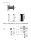
voltage is 60V. The transformer voltages are shown in Figures 7 and 8; the physical dimensions are
shown in Figure 6. For other transformers, contact the factory.
CLOCK
DIRECTION
MODE SELECT
MOTOR
ON/OFF
0VDC
01
03
1,3 COM
2,4 COM
02
04
10
4
7
6
5
8
9
EXTERNAL
PULSE
GENERATOR
SW1
1 RED
2 R/W
3 BLK
11 WHT
12 GRN
13 G/W
6 LEAD-4 PHASE
STEP MOTOR
SW2
SW3
0
50
100
ANAHEIM
AUTOMATION
KICK
CURRENT
ADJUST
SEE
SILKSCREEN
N/C
AA2791
TRANSFORMER
LOW
HIGH
RED
YEL/
YEL/
BLK
115 VAC
QD1
QD2
QD3 QD4
WHT/BLK
BLACK
RED/
BLK
BLU
RESET
Figure 5: Hook Up Drawing