3
P
OWER
O
UTPUT
&
C
ONNECTORS
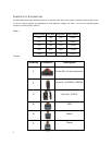
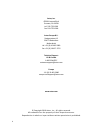
The HCG-520 power supply distributes power on separate rails. Some rails require a minimum load in order to run.
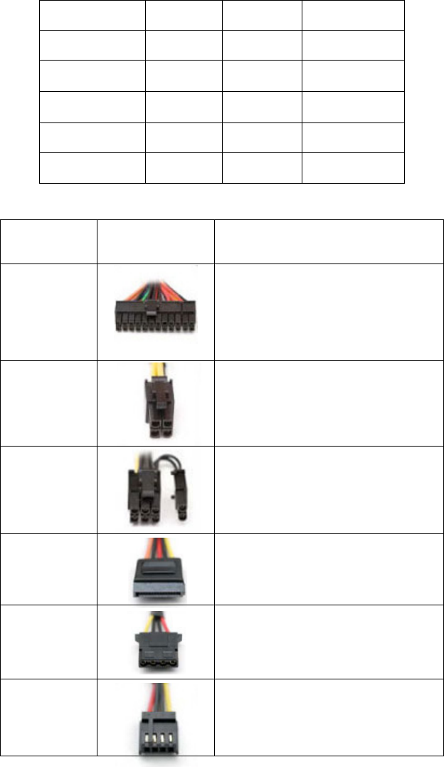
To see the output capacity and regulation for each different voltage, see Table 1. A list of all available power
connectors can be found in Table 2.
T
ABLE
1
Output Voltage Load Max. Regulation Ripple & Noise
+3.3V 24A ±5% < 50 mV
+5V 24A ±5% < 50 mV
+12V 40A ±5% < 120 mV
–12V 0.8A ±10% < 120 mV
+5VSB 2.5A ±5% < 50 mV
T
ABLE
2
Quantity Connector Description
1
24-pin (20 + 4) main connector
1
8-pin (4 + 4) ATX12V / EPS12V
2
8-pin (6 + 2) PCI-E
6
SATA
6
Molex
1
Floppy


