


3
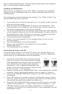
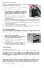
Connecting the USB Ports
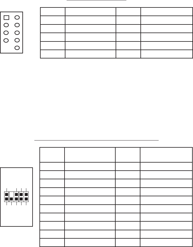
You will find a single 10-pin connector on a cable attached to the front USB ports.
This is an Intel standard connector which is keyed so that it can’t be accidentally,
reversed as long as it is connected to a proper Intel standard motherboard header.
Connect the 10-pin connector to the motherboard headers so that the blocked pin
fits over the missing header pin.
Note: Please check the motherboard manual for the USB header pin layout and
make sure it matches the table below. If it does not match this Intel® standard,
please visit Antec’s web store at http://www.antec.com/StoreFront.bok and
search for part number 30095 to order a USB Internal Adapter Cable. This adapter
will allow you to connect the front USB to your motherboard on a pin-by-pin basis.
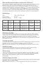
Motherboard Pin Layout
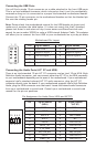
Connecting the Audio Ports (AC’ 97 and HDA)
There is an Intel standard 10-pin AC’ 97 connector and an Intel 10-pin HDA (High
Definition Audio) connector, you can connect either the AC’ 97 or the HDA connector
to your motherboard depending on the spec of the motherboard. If your motherboard
supports Intel’s standard onboard AC’ 97 audio connector, plug the AC’ 97
connector directly onto the board. If your motherboard supports Intel’s High Definition
Audio, plug the HDA connector onto the board. Locate the internal audio connectors
from your motherboard or sound card. Consult your motherboard or sound card
manual for the pin-out positions.
Pin Assignment for Audio Ports (HDA and AC’97)
Pin Signal Names Pin Signal Names
1
USB Power 1
2
USB Power 2
3
Negative Signal 1
4
Negative Signal 2
5
Positive Signal 1
6
Positive Signal 2
7
Ground 1
8
Ground 2
9
Key (No Connection)
10
Empty Pin
12
10
9
Pin Signal Names
(HDA)
Pin Signal Names
(AC’97)
1 MIC2 L 1 MIC In
2 AGND 2 GND
3 MIC2 R 3 MIC Power
4 AVCC 4 NC
5 FRO-R 5 Line Out (R)
6 MIC2_JD 6 Line Out (R)
7 F_IO_SEN 7 NC
8 Key (no pin) 8 Key (no pin)
9 FRO-L 9 Line Out (L)
10 LINE2_JD 10 Line Out (L)
1
2
3579
46
10