


3
Motherboard Pin Layout
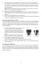
Connecting the Audio Ports (AC’97 and HDA)
There is an Intel standard 10-pin AC’97 connector and an Intel 10-pin HDA (High
Definition Audio) connector. You can connect either the AC’97 or the HDA connector
to your motherboard depending on the spec of the motherboard. If your motherboard
supports Intel’s standard onboard AC’97 audio connector, you can plug the
AC’97 connector directly into the board. If your motherboard supports Intel’s High
Definition Audio, you can plug HDA onto the board. See instruction below:
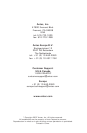
Pin Assignment for Audio Ports (HDA and AC’97)
Locate the internal audio connectors from your motherboard or sound card. Consult
your motherboard or sound card manual for the pin-out positions.
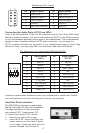
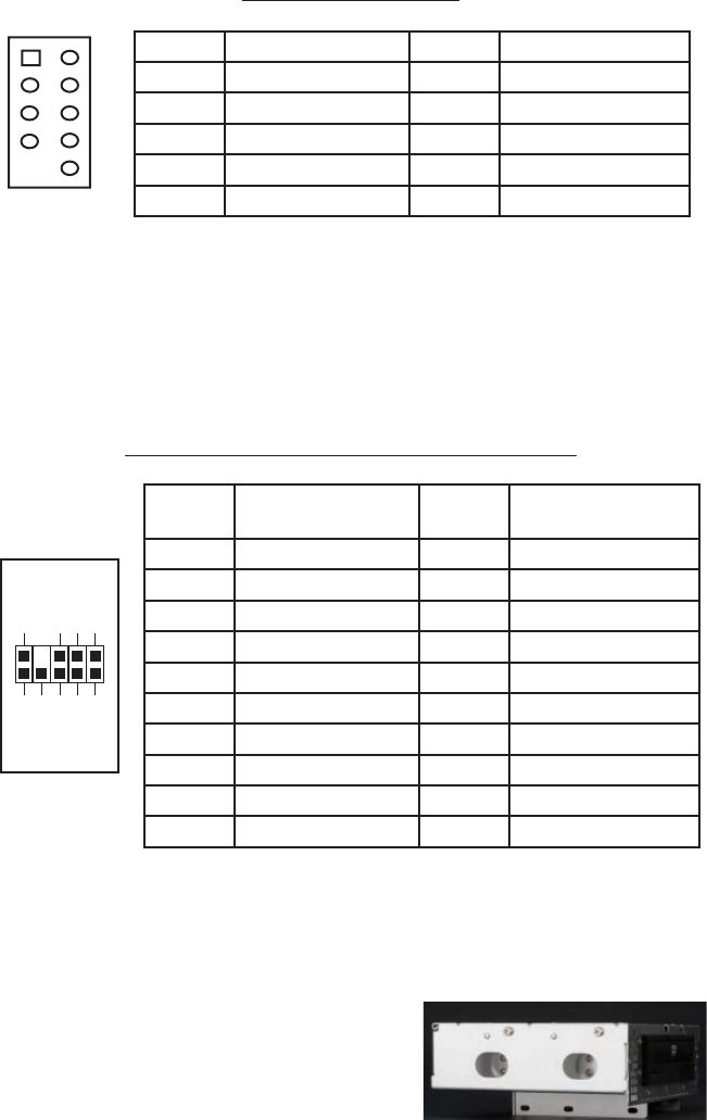
Hard Disk Drive Installation
The NSK1380 incorporates a rapid-release
Flip Up Drive Cage for easy drive installation.
The cage includes up to four drive bays:
one external 5.25”, three internal 3.5”.
To install the external 5.25” device:
1. Remove the flip-up drive cage.
2. Insert the 5’25” device and align the
screw holes to the front set of holes
on the cage. Fasten the drive with the
screws included. (See Picture 3)
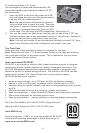
Pin Signal Names Pin Signal Names
1
USB Power 1
2
USB Power 2
3
Negative Signal 1
4
Negative Signal 2
5
Positive Signal 1
6
Positive Signal 2
7
Ground 1
8
Ground 2
9
Key (No Connection)
10
Empty Pin
12
10
9
Pin Signal Names
(HDA)
Pin Signal Names
(AC’97)
1 MIC2 L 1 MIC In
2 AGND 2 GND
3 MIC2 R 3 MIC Power
4 AVCC 4 NC
5 FRO-R 5 Line Out (R)
6 MIC2_JD 6 Line Out (R)
7 F_IO_SEN 7 NC
8 Key (no pin) 8 Key (no pin)
9 FRO-L 9 Line Out (L)
10 LINE2_JD 10 Line Out (L)
1
2
3579
46
10
Picture 3