


2
Installing the Motherboard
This manual is not designed to cover CPU, RAM, or expansion card installation.
Please consult the motherboard manual for specific mounting instructions and
troubleshooting.
The motherboard is located inside the main chamber with two 80 mm TriCool TM
fans preinstalled right next to the CPU.
1. Lay the case down, with the open side facing up. The drive cages and power
supply should be visible.
2. Make sure you have the appropriate I/O panel for the motherboard. If the
panel provided is not suitable for the motherboard, please contact the
motherboard manufacturer for the correct I/O panel.
3. Remove the cross bar on the motherboard chamber.
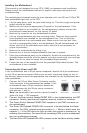
4. Line up the motherboard with the mounting holes. There are three special
brass standoffs pre-installed on the motherboard tray. Two of them are
threaded and one is an unthreaded post. Make note of any that don’t line
up with a corresponding hole in the motherboard. Not all motherboards will
match with all of the provided screw holes, and this is not necessary for
proper functionality.
5. Remove the motherboard by lifting it up.
6. Remove any of the pre-installed standoffs that aren’t needed.
7. Place the motherboard back on the standoffs. Attach the motherboard to the
threaded brass standoffs with the special nuts that comes with your tool bag.
Note: You do not need to fasten the unthreaded brass standoff.
8. Fasten the rest of the standoffs with the provided Philips-head screws. The
motherboard is now installed.
Connecting the Power and LED
If the motherboard has a 20-pin power receptacle, detach the 4-pin attachment
on the 24-pin power connector. Before you connect the power supply to any of
the devices, please consult the appropriate user manuals for the motherboard and
other peripherals.
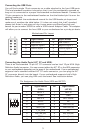
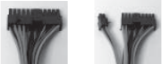
1. Connect the 24-pin Main Power Connector and the
4-pin connector to the motherboard as needed. If the
motherboard uses a 20-pin connector; detach the
4-pin attachment on the 24-pin power connector
(see pictures 1 and 2).
Note: the detachable 4-pin section cannot be used in
place of a 4-pin +12V connector.
2. Connect the Reset switch (labeled RESET SW) to the motherboard at the RST
connector. Polarity (positive and negative) does not matter for switches.
3. The Power Switch (labeled POWER SW) connects to the PWR connector on
the motherboard.
4. The Power LED (labeled POWER LED) connector is located behind the Reset
connector. For LEDs, colored wires are positive (+). White or black wires are
negative (–). If the LED does not light up when the system is powered on, try
reversing the connection. For more info on connecting LEDs to your motherboard,
see your motherboard manual.
5. The Hard Drive LED (labeled HDD LED) connects to the hard drive activity header.
Picture 1 Picture 2
For 24-pin
motherboards
For 20-pin
motherboards