


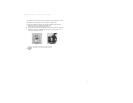
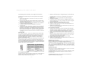

Installing the Motherboard
This manual is not designed to cover CPU, RAM, or expansion card installation.
Please consult your motherboard manual for specific mounting instructions and
troubleshooting.
1. Lay the case down, with the open side facing up. The drive cages and
power supply should be visible.
2. Make sure you have the correct I/O panel for your motherboard. If the
panel provided with the case isn't suitable, please contact your
motherboard manufacturer for the correct I/O panel.
3. Line up your motherboard with the standoff holes, and remember which
holes are lined up. Not all motherboards will match with all of the provided
holes; this is normal, and won't affect functionality. (In other words, there
will likely be extra holes.)
4. Remove your motherboard by lifting it up.
5. Screw the brass standoffs into the threaded holes that line up with your
motherboard. Do not overtighten the standoffs. Some standoffs may be
pre-installed for your convenience.
6. Place your motherboard on the brass standoffs.
7. Screw in your motherboard to the standoffs with the provided Phillips-head
screws. Your motherboard is now installed.
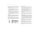
Connecting the Power and LED
The Antec SmartPower power supply is an ATX12V form factor power supply
with a single 20-pin Main Power Connector, a 6-pin AUX Power Connector, and
a 4-pin +12V Power Connector for the motherboard. It also includes 2 SATA
connectors, five to seven 4-pin Peripheral Power Connectors and one to two
4-pin Floppy Drive Power Connectors for your drives. It is backwards compatible
to previous ATX form factor power supplies. If your motherboard does not
support the AUX Power Connector or the +12V Power Connector, you can still
use this power supply.
The power supply is also equipped with a 3-pin fan signal connector. Connect it
to one of the fan connectors on your motherboard. You may monitor the speed
of the rear power supply fan through your motherboard BIOS or through the
monitoring software that's supplied with your motherboard. Note: At low
temperatures, the fan may run as slow as 1200 RPM. At these speeds, some
motherboards may not properly detect the fan speed and may generate false
warnings of fan failure. To ensure proper monitoring of the fan, please check
your motherboard manual.
1. Connect the 20-pin ATX power connector (and AUX or +12V connectors
if appropriate) to your motherboard.
2. Connect the Reset switch (labeled RESET SW) to your motherboard at the
RST connector. Make sure the label always faces the front of the case.
3. Connect the Power Switch (labeled POWER SW) to the PWR connector on
your motherboard.
4. You'll find the Speaker connector (labeled SPEAKER) behind the PWR
connector.
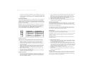
5. The Power LED, Hard Drive LED, LED I & LED II connectors all share a
single ribbon cable. Attach the Power LED (labeled POWER) and HDD LED
At Antec, we continually refine and improve our products to ensure the highest
quality. So it's possible that your new case may differ slightly from the descriptions
in this manual. This isn't a problem; it's simply an improvement. As of the date of
publication, all features, descriptions, and illustrations in this manual are correct.
SLK1650 & SLK1650B – Mini Tower Case
Power Supply
Your new case features a whisper-quiet 350 Watt SmartPower power supply,
with a main power switch. Make sure you turn the switch to the ON ( I )
position before you boot up your computer for the first time. Normally, you
won't need to switch to the OFF (O) position, since the power supply includes a
soft on/off feature. This lets you turn your computer on and off by using the
soft switch on your computer case. If your computer crashes and you can't
shut it down using the soft switch, you can switch the main power to the OFF
(O) position.
Note [Applies only to models designed for sale in the European Union:
SmartPower models designed for the EU include Power Factor Correction (PFC)
circuitry in accord with European standard regulation code EN61000-3-2. By
altering the input current wave shape, PFC improves the power factor of the
power supply. This results in increased energy efficiency, reduced heat loss,
prolonged life for power distribution and consumption equipment, and improved
output voltage stability.]
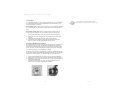
Note (not applicable to models designed for the European Union): Before
installation, check the red voltage switch setting on the power supply. It
should match your local voltage (115V for North America, Japan, etc. and
230V for Europe and many other countries). If it doesn't match, please
change the setting. If you don't, you could damage your equipment and
void your warranty.
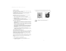
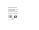
Setting Up
1. Place the case upright on a flat, stable surface. The power supply fan
(at the back) should be facing you.
2. Remove the two thumbscrews which fasten the top cover. These are the
only screws you need to remove to open the case. Set these screws aside
and keep them separate from the other screws.
3. Slide the top panel toward the rear of the case and lift it up to remove.
4. At the top of the each side panel, in front of the power supply, there is a
4" wide tab. Lift this tab and pull the side panel out to remove.
5. Inside the case you should see the power supply, some wiring (LED's, etc.),
an installed I/O panel, a power cord and a plastic bag containing more
hardware (screws, brass standoff, plastic stands, etc.).
Disclaimer
This manual is intended only as a guide for Antec's Computer Enclosures. For more comprehensive
instructions on installing your motherboard and peripherals, please refer to the user's manuals which
come with your components and drives.
1
2
SLK1650_Manual_intl.qxd 5/14/2004 3:49 PM Page 6