


connectors to the appropriate headers on your motherboard. You can use
the LED I and LED II connectors as you see fit: as SCSI LED, Message LED,
etc. or any other function supported by your motherboard, expansion cards,
and peripherals.
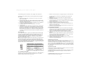
Connecting the USB Ports
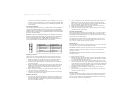
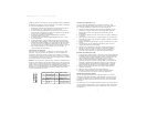
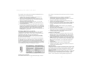
You will find a single 10-pin connector on a cable attached to the front USB ports.
This is an Intel standard connector which is keyed so that it can't be accidently
reversed as long as it is connected to a proper Intel standard motherboard header.
Connect the 10-pin connector to your motherboard headers so that the blocked pin
fits over the missing header pin.
Note: Please check your motherboard manual for your USB header pin layout and
make sure it matches the attached table. If it does not match this Intel standard,
please call Antec customer service at (888) 54ANTEC (North America) or
+31 (10) 462-2060 (Europe) for a USB adapter. This adapter will allow you to
connect the front USB to your motherboard on a pin-by-pin basis.
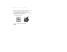
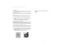
Installing 3.5" Devices
There is one 3.5" drive cage inside the case. The upper portion can hold 2
external 3.5" drives, and the lower portion can hold 3 internal 3.5" drives.
1. Mount your external 3.5" drives into the top two drive bays. Load the
drives from the back, lining them up to the front of the drive cage.
2. Use one hand to support the drive, and fasten the drive to the cage with
the screws provided.
3. Mount your hard drive or other internal 3.5" device into the drive cage by
threading the special screws through the rubber grommets. Don't over-
tighten the screws, since that could decrease the grommets' ability to
reduce vibration and noise.
6. Find a small 4-pin connector on the power supply and connect it to the
male 4-pin connector on the floppy drive.
7. Connect a 4-pin large connector from the power supply to the male 4-pin
connector on each of the other devices.
Installing 5.25" Devices
1. If you look into the 5.25" drive bays from above the power supply, you'll
see some metal grilles covering the front of those bays. Carefully push a
screwdriver through the metal grille, and gently remove the plastic drive
bay cover by pushing outwards.
2. Use your hands to twist the metal plate back and forth until it breaks off.
Note: Don't break off the metal grilles covering the drive bays that you
don't intend to use now. Be careful of the newly exposed metal where the
grille was attached, as these areas are likely to be sharp.
3. Using the screws provided, fasten your 5.25" device into the drive bay.
4. Repeat the same procedure for other devices.
5. Connect a 4-pin large connector from the power supply to the male 4-pin
connector on each of the devices.
Connecting the Data Cables
After you've connected the devices to the power supply, you need to connect
data cables between the devices and the motherboard. To achieve the best
data-transfer and cooling performance, we recommend using premium rounded
cables such as Antec Cobra Cables.
The cables that are included with your drives should have a red strip on one
side indicating pin number 1. If you use these cables, make sure that the red
strip is on pin 1, usually toward the power connector.
Installing the Fan
We've included one rear-mounted 120mm exhaust fan. In the front of the case,
you'll also find a mount for an optional 80mm intake fan.
The rear fan is installed so that the air blows out of the case. Find a large 4-pin
peripheral connector on the power supply and connect it to the male 4-pin
connector on the fan.
The front fan (optional) should be installed so that the air is blowing into the
case from the front.
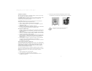
To mount the optional front fan:
1. Squeeze the upper right and left sides of the fan cage together to release
the tabs. Once the cage is loose, slide it upwards. You should then be able
to pull the cage back and out of the case.
2. Drop the fan into the cage from the case's front side, and push it in until
the four tabs snap the fan in place. We recommend routing the fan's power
wires through any of the slots near each corner of the fan cage. (Make sure
you don't pinch the wires.) No screws are needed. The front fan should be
installed so that the air is blowing into the case.
3. Reattach the cage/fan assembly to the case, taking care not to pinch
the fan wires.
4. Connect a large 4-pin connector from the power supply to the male 4-pin
connector on each of the fans.
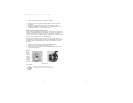
Chassis Air Guide
Your new case includes a chassis air guide, which provides cooling air directly
to the CPU. The air guide consists of three parts: an upper duct, flange, and
lower duct. If you prefer, you can adjust the distance between the lower duct
and your CPU for maximum cooling efficiency.
3
4
12
910
Pin Signal names Pin Signal names
1 USB Power 1 2 USB Power 2
3 Negative Signal 1 4 Negative Signal 2
5 Positive Signal 1 6 Positive Signal 2
7 Ground 1 8 Ground 2
9 Key (No Connection) 10 Empty Pin
SLK1650_Manual_intl.qxd 5/14/2004 3:49 PM Page 8