


4
3
the toolbox in case you later need to cover drive bays again.
3. Take two drive rails and mount them to the sides of your
5.25" device.
4. Slide the device into the drive bay until you hear a click.
5. Repeat the same procedure to install your other drives.
6. Connect a large 4-pin white connector from the power
supply to the male 4-pin connector on each device.
7. After you have finished installing devices, carefully use
your thumbs to push the plastic drive bay covers off the
bezel and re-attach the bezel to the case.
Data Cable Connection
After you have connected the devices to the power supply, you need to connect the data
cables between the devices and the motherboard. The data cables are not included with the
case; we include this information only as an aid.
1. For hard drives and CD-ROM's, use the 40-pin IDE ribbon cables. For floppy drives,
use the 34-pin ribbon cables. These should come with your devices and have a red
strip on side indicating pin number 1. When you connect a ribbon cable to a device,
make sure that the red strip is on pin 1, usually toward the power connector.
2. The side that attaches to devices should be the side that has 2 connectors. This will
enable you to connect another device if you wish.
3. Connect the far end of the cable to your motherboard on the IDE port, either IDE 1
or IDE 2, or the FLOPPY port.
Fan Installation
The case has one 120mm cooling fan mounted in the rear and one optional 120mm cooling
fan mount in the front.
The rear fan is installed so that the air is blowing out of the case.
Connect a large 4-pin white connector from the power supply to the male 4-pin connector
on the fan.
The front fan should be installed so that the air is blowing into the case from the front.
It is recommended that you install the fan while the lower 3.5" drive cage is removed from
the case.
1. Drop the fan into the fan cage and push it in until it snaps in.
2. If you're using a 4-pin fan connect a large 4-pin white connector from the power
supply to the male 4-pin connector on the fan. If you're using a 3-pin fan connect the
3-pin connector to a motherboard fan header.
Washable Air Filter Maintenance
We recommend washing the air filter as often as required by environmental conditions, at
least once a month initially. Failure to keep the installed air filter clean will result in higher
system temperatures and possible stability problems.
Antec Quality 3-Year parts and labor warranty (AQ3)
See details at:
http://www.antec-inc.com/support_warranty.html
http://www.antec-europe.com/warranty_uk.html
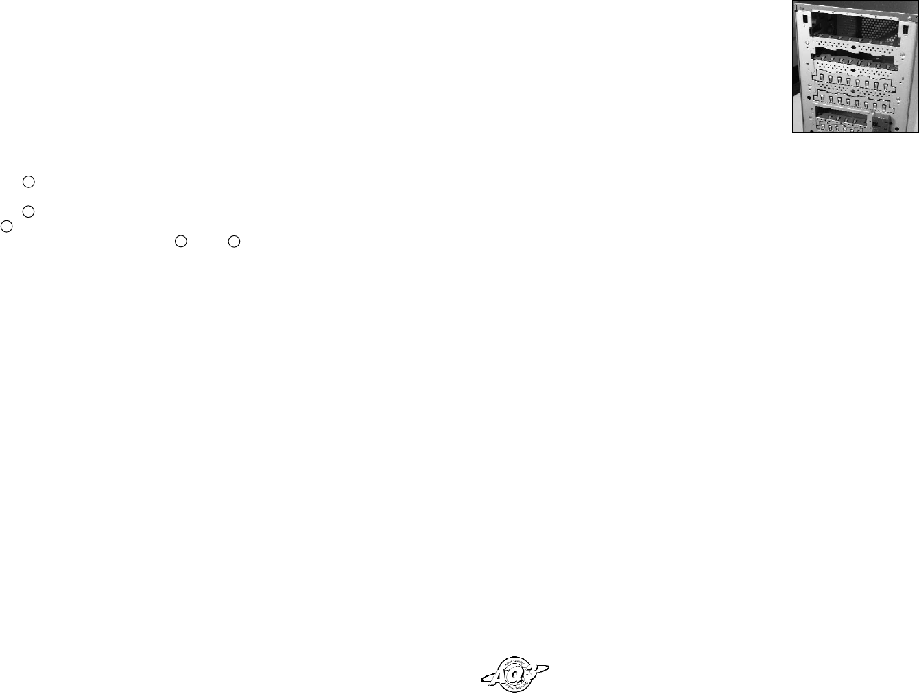
Picture 1.
2. Consult your motherboard manual to get each of the pin-out positions.
3. Power Pins: There are two power pins, one on each row. They are usually marked as
Power, Vcc or +5V. Connect the two +5V connectors to the two power pins. Each
connector can go to either pin.
4. Ground Pins: There are two ground pins, one on each row. They are usually marked
as GROUND or GND. Connect the two GROUND connectors to the two ground pins.
Each connector can go to either pin.
Note: On some motherboards, there may be two ground pins on one row. You don't
need to use all of them. Make sure to connect one ground pin on each row.
5. Data Pins: There are two plus data pins, one on each row, and two minus data pins,
one on each row. They are usually marked as USBD2+, USBD3+ and USBD2-,
USBD3- or USBP2+, USBP3+ and USBP2-, USBP3- respectively.
a. Connect the 1 +D connector to any of the two plus data pins. It can go to either
of the plus pins.
b. Connect the 1 -D connector to the minus data pin in the same row as the plus data
pin that 1 +D connector has just connected to.
c. Repeat the same procedures to connect the 2 +D and 2 -D to the motherboard.
Make sure they are in the same row.
3.5" Device Installation
There are two 3.5" drive cages inside the case. The upper one can hold 2 external 3.5"
drives, and the lower one can hold 5 internal 3.5" drives. Release the upper cage by pulling
the quick release lever towards the rear of the case. Unscrew the thumbscrew on the bottom
of the lower cage and press the release tab to release the drive cage. To remove the lower
drive cage pull the drive cage out of the opening. Note: Many removable drive cages had
you pull the cage towards the back of the case. This is NOT the case for the lower drive
cage. Put both cages on a flat surface.
1. Mount your floppy drives or other external devices into the upper cage.
2. Mount your hard drive or other internal 3.5" devices into the lower drive cage with
the special screws provided. Don't over-tighten the screws since the hard drives are
mounted to the cage by the screws through the rubber grommets.
3. Slide and lock both drive cages back into the case.
4. Find a small 4-pin white connector on the power supply and connect it to the male
4-pin connector on the floppy drive.
5. Connect a large 4-pin white connector from the power supply to the 4-pin connector
on each of the other devices.
Note: If you want to install a 120mm fan to the front of the case, you should do so
before re-installing the lower drive cage in the case. See Fan Installation section for
details.
5.25" Device Installation
There are four 5.25" drive bays, each covered with a ventilated metal cover and an EMI
Contact plate as one Assembly. For your convenience the factory has prepared the top drive
bay without the metal plate so that it is ready for immediate installation. To install a 5.25"
drive in another bay:
1. Bend the EMI Contact plate covering the Lower half of the selected drive bay 90
degrees inwards to form a drive support. (See picture 1.)
2. Carefully twist the assembly covering the upper half of the selected drive bay back
and forth until it breaks off, and remove it.
Note: Be careful of the newly exposed metal where the assembly was attached as
these areas are likely to be sharp. Don't break off the metal assemblies covering the
drive bays that you are not using now. Antec has included two EMI cover plates in