


3
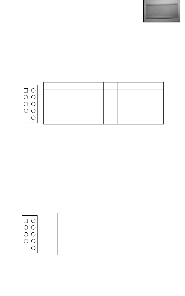
rack, please use the clear plastic film that came with the toolbox to cover
the ventilation (see picture 3). This can prevent hot air in the cabinet from
entering the system and causing heat related system problems.
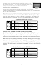
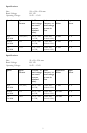
CONNECTING THE USB PORTS
You will find two 4-pin connectors on cables attached to the front USB ports.
Connect the 4-pin connectors to your motherboard headers so that the USB Power pins match
the VCC pins on the connectors.
Note: Please check your motherboard manual for your USB header pin layout and make sure it
matches the attached table. If it does not match, please call Antec customer support at (800)
22ANTEC (North America) or at +31 (0) 10 462-2060 (Europe) to buy a USB adapter. This
adapter will allow you to connect the front USB to your motherboard on a pin-by-pin basis.
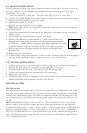
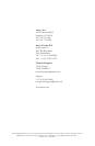
CONNECTING THE IEEE 1394 (FIREWIRE®, I.LINK®) PORT
You will find a single 10-pin connector on a cable attached to the front IEEE 1394 connection.
This is an Intel standard connector, which is keyed so that it can't be accidentally reversed as
long as it is connected to a proper Intel standard motherboard header. Connect the 10-pin
connector to your motherboard header so that the blocked pin fits over the missing header pin.
Note: Please check your motherboard manual for your IEEE 1394 header pin layout and make
sure it matches the attached table. If you intend to connect the front FireWire port to an IEEE
1394 add-on card that comes with an external-type IEEE1394 connector, please call Antec
customer support at (800) 22ANTEC (North America) or +31 (0) 10 462-2060 (Europe) to buy
an adapter. This adapter will allow you to connect the front IEEE 1394 port to the external-type
connector.
Pin
Signal Names Pin Signal Names
1
3
5
7
9
2
4
6
8
10
USB Power 1
Negative Signal 1
Positive Signal 1
Ground 1
Key (No Pin)
USB Power 2
Negative Signal 2
Positive Signal 2
Ground 2
Empty Pin
Intel Standard USB Header Pin Layout
1
2
9
10
Pin Signal Names Pin Signal Names
1
3
5
7
9
2
4
6
8
10
TPA+
Ground
TPB+
+12V (Fused)
Key (No Pin)
TPA–
Ground
TPB–
+12V (Fused)
Ground
Standard Pin Assignment for IEEE 1394 Connector
1
2
9
10
Picture 3