


6
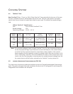
Pin
Signal
Names
Pin
Signal
Names
1
USB
Power
1
2
USB
Power
2
3
Negative
Signal
1
4
Negative
Signal
2
5
Positive
Signal
1
6
Positive
Signal
2
7
Ground
1
8
Ground
2
9
Key
(No
Connection)
10
Empty
Pin
2.6 E
XTERNAL
3.5”
D
EVICE
I
NSTALLATION
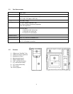
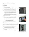
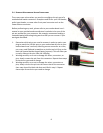
There is one 3.5” drive bay available just below the 5.25” drive bays at
the front of the case. Before you begin, remove the side panels and
front bezel of the case as described in section 2.1.
1.
Slide your 3.5” device into the drive bay from the front and align
the screw holes on the devices with the corresponding holes in
the chassis.
2.
Fasten the device in place with the provided screws.
3.
Connect the appropriate power and data cables.
2.7
E
XTERNAL
5.25”
D
EVICE
I
NSTALLATION
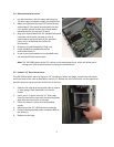
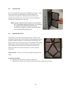
There are three externally accessible 5.25” drive bays. Before you
begin, remove both side panels and front bezel as detailed in section
2.1.
1. Remove the drive bay faceplate by applying pressure to the
inside of the plate until it pops free of the bezel.
2. Slide your 5.25” device into the bay from the front of the case.
3. Secure the drive into position in the drive cage using the
provided screws.
4. Mount any other 5.25” devices accordingly.
5. Connect the appropriate power and data cables to your
device(s).
C
ONNECTING THE
F
RONT
I/O
P
ORTS
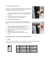
3.1
USB
2.0
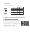
Connect the front I/O panel USB cable to the USB header pin on your motherboard. Check your
motherboard user’s manual to ensure that it matches the table below:
1 2
9 10