


5
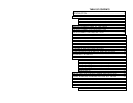
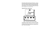
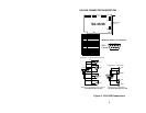
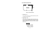
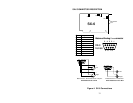
SX-35/36 CONNECTOR DESCRIPTION
JP1
SX-35/36
JP4
JP7
JP8
JP9
BALANCED
IN/OUT
JP3
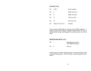
Pin Assignment
1Ground
2 Right In -
3Left In-
4Right Out -
5Left Out -
6 Right In +
7 Left In +
8Right Out +
9Left Out +
DB-9
Female
Balanced Analog I /O Connector
12345
6789
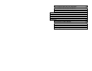
SX-35/36 Balanced I/O to XL
R
12345
6789
Balanced In - XLR male shell, female pin
s
Left
Right
1
- 2
+ 3
GND
Right
Balanced Out - XLR female shell, male pins
1
1
1
+ 3
Left
- 2
- 2
+ 3
- 2
+ 3
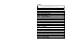
SX-35/36 Unbalanced I/O to RC
A
12345
6789
Left
Unbalanced Out - Female RCA
Right
Left
Right
Unbalanced In - Female RCA
Figure 2. SX-35/36 Connections