


4 Smart-UPS RT 2400/3000 VA Tower/Rack-Mount UPS User Manual
Installation
Installation
Refer to instructions below for information on how to install the UPS in a rack, in a tower configuration, or
when installing the UPS with optional battery pack(s). Once the UPS has been placed in the desired tower or
rack location, complete the remaining installation steps in sequential order, beginning with “Connect
Equipment to the UPS” on page 4.
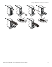
To Install the UPS in a Rack
See the installation sheet supplied with the optional rail kit (SURTRK2) to install the UPS in the rack. It is
recommended that you remove the battery before attempting to install it in the rack. See “To Install a
Replacement Battery” on page 12 for the procedure.
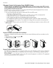
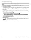
To Install the UPS in a Tower Configuration
For stability, the UPS is shipped with stabilizing feet. Using the UPS in a tower configuration without
the feet may result in bodily injury or equipment damage.
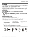
To Install the UPS with External Battery Pack(s)
In addition to the UPS, if your configuration includes optional Smart-UPS RT battery pack(s)
(SURT192XLBP, SURT192XLBPJ), see the battery pack user manual to complete the physical installation
for the UPS with external battery pack(s).
The UPS must be installed above external battery pack(s) when in a rack. When installing the UPS in a
tower configuration, battery pack(s) must be installed to the right of the UPS when facing the front of the
UPS. Failure to follow these instructions could result in cabling shortage.
Connect Equipment to the UPS
Prior to connecting the grounding cable, ensure that the UPS is NOT connected to utility or battery
power circuits. See step 1 on page 5 for procedure.
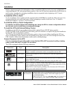
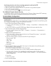
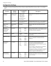
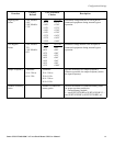
The UPS is equipped with the following connectors.
Connectors Type Description
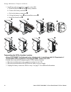
Serial Com Use only the supplied cable to connect to the serial port.
NOTE: A standard serial interface cable is incompatible with the UPS.
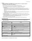
Normal bypass Manual bypass enables the user to manually put connected equipment into
bypass mode.
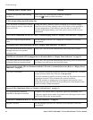
EPO terminal The Emergency Power Off (EPO) terminal allows the user to connect the UPS
to the central EPO system.
N
OTE: Adhere to national and local codes when wiring the EPO switch.
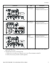
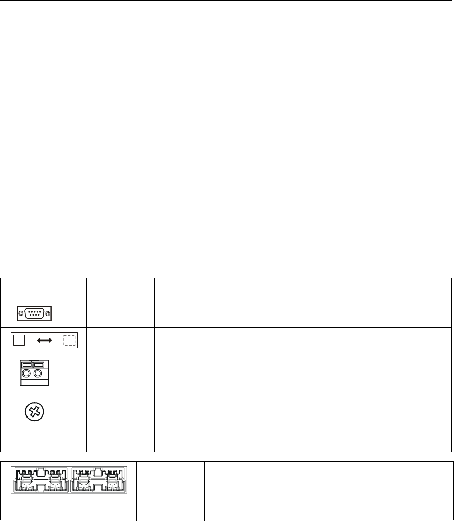
TVSS screw The UPS features a Transient Voltage Surge-suppression (TVSS) screw located
on the rear panel, for connecting the ground cable on surge suppression devices
such as telephone and network line protectors.
N
OTE: Prior to connecting the grounding cable, disconnect the UPS from the
utility power outlet and turn off the UPS.
External battery
pack connector
Optional Smart-UPS RT external battery packs provide extended
run-time during power outages. These units support up to ten
external battery packs.
N
OTE: See the APC Web site, www.apc.com for information on
the external battery pack, SURT192XLBP, SURT192XLBPJ.