


6739381EN/
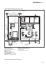
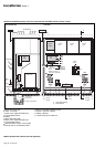
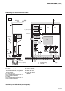
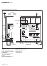
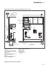
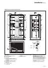
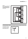
1200kVA external maintenance bypass cubicle
Key to figure:
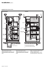
AA: cross-section AA of cubicle,
B: cubicle front view,
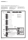
C: front panel,
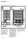
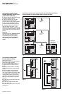
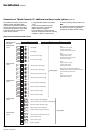
E: connection of auxiliary wires to
signal the position of switches Q5N
and Q3BP,
F: connection of UPS load outputs,
G: connection of the maintenance
bypass line,
H: connection of load,
I: air outlet grid,
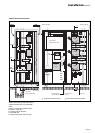
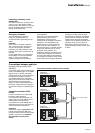
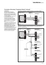
Important. The power cables between
each UPS and the upstream
protection devices must be the same
length. The same holds for the power
cables between each UPS cubicle and
the external maintenance bypass.
TNC option: connection of the PEN
conductors to the UPS neutral bar.
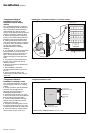
J: openings of 460 x 204 mm for cable
insertion,
L: top view of cubicle.
C
AA
A
A
B
Q5N
G
F
H
XM8
MISI 1
1
2
Q3BP +
Q3BP -
XM8
MISI 2
1
2
Q3BP +
Q3BP -
MISI 3
MISI 4
E
Q3BP
12
L
H
Q5N
G
I
J
Q3BP
E
F
E
Installation (cont.)