User Manual Back-UPS
®
BE550G/BE700G
Caution
• For safety, the Back-UPS ES is shipped with one battery wire disconnected. Small sparks may occur during battery
connection.
• Do not install the unit in direct sunlight, in excessive heat or humidity, or in contact with fluids.
• Connect the power cord directly to a wall outlet; not a surge protector or power strip. The outlet
must be located near the equipment and easily accessible.
Connect the Battery
Overview
Turn on the Back-UPS
Press the ON/OFF switch to turn the unit ON. A single short beep and the green “Power On” indicator confirms that
Back-UPS ES is on and ready to provide protection. The UPS will automatically perform a self-test when power is
applied to the unit, the green LED will flash during the self-test.
Note: Prior to first use, charge the Back-UPS for at least 16 hours to ensure sufficient runtime. The unit is charging
whenever it is connected to utility power, whether the unit is turned ON or OFF.
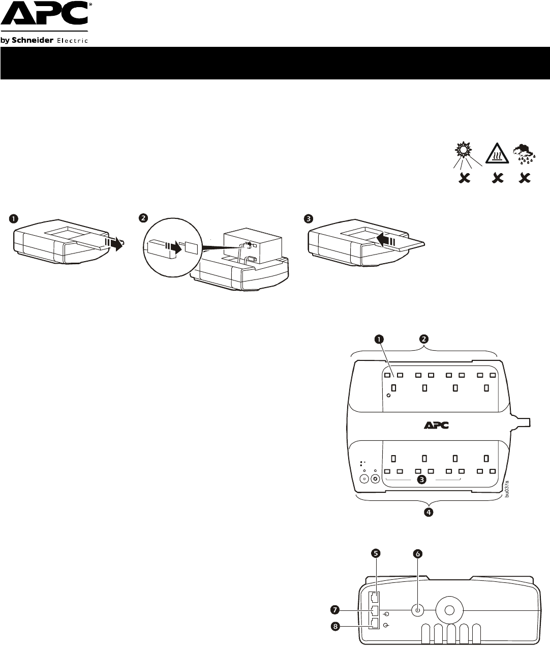
1
Master Outlet—Connect a master device, such as a computer. See
“Using the power-saving outlets” on page 2.
2
Battery Backup and Surge Protection—These outlets receive
power whenever the unit is ON. During a power outage or other
utility problems (brownouts, over-voltages), these outlets will
receive power from the unit for a limited time. Connect a computer,
monitor, and two other data-sensitive devices into these outlets.
Note that one of these outlets is the Master outlet. See “Using the
power-saving outlets” on page 2.
3
Controlled Outlets—Connect peripheral devices. See “Using the
power-saving outlets” on page 2.
4
Surge Protection—These outlets provide full-time protection from
surges even if the unit is OFF, but will only supply power when the
unit is ON. Connect a printer, fax machine, scanner, or other
peripherals that do not need battery power during power outages.
Note that if the power-saving feature is enabled, three of these
outlets are controlled by the Master outlet.
5
Data Port—Use the supplied RJ45/USB cable to connect the Back-
UPS unit to a computer to install the software. See “Install the
PowerChute® Personal Edition software” on page 2.
6
Circuit Breaker—Push to re-set the circuit breaker.
7
Modem/Phone/Fax—Connect a DSL or dial-up modem, phone,
fax machine, or 10/100 Base-T ethernet equipment. Note: Do not
connect the UPS telephone protection ports to both the
telephone and network system cables at the same time.
8
Wall outlet—Connect the unit to a data line wall outlet.
