


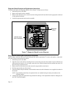

Diagnostic Board Removal and Replacement Instructions
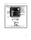
To remove and replace the Diagnostic Board, refer to Figure 7 and proceed as follows:
1. Disconnect power to the SPD.
2. Remove the board from the standoffs.
3. Remove the connectors one at a time from the existing board and insert them into the appropriate connector
on the replacement board.
4. Install the replacement board onto the standoffs.
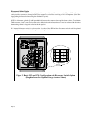
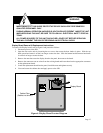
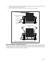
Surge Module Removal and Replacement Instructions
Surge modules within the SPD may become damaged and require replacement. To remove and replace a surge mod-
ule, refer to Figure 8 and proceed as follows:
1. Disconnect power to the SPD.
2. Open the door on the unit by loosening the two screws that secure the door latches in place. Slide the top
latch upward and rotate it so it no longer secures the door. Slide the bottom latch downward and rotate it so
that it no longer secures the door.
3. Remove the two allen-head screws that secure the surge module to the chassis.
4. Pull the surge module out of the chassis.
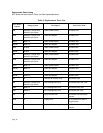
1RWHWKHORFDWLRQDQGSDUWQXPEHURIHDFKPRGXOHUHPRYHGDVWKLVLQIRUPDWLRQLVQRWVXSSOLHGHOVHZKHUHLQ
WKHFDELQHW
127(6XUJH0RGXOHVVKRXOGRQO\EHUHSODFHGZLWKDQHZPRGXOHKDYLQJWKHVDPHSDUWQXPEHUDVWKH
UHPRYHGPRGXOH
8QSDFNDQGLQVSHFWWKHUHSODFHPHQWVXUJHPRGXOHIRUGDPDJH,IWKHUHSODFHPHQWPRGXOHLVGDPDJHGFRQ
WDFW$3&7HFKQLFDO6XSSRUW
3DJH
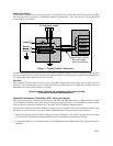
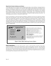
)LJXUH'LDJQRVWLF%RDUG/RFDWRU'LDJUDP
Diagnostic
Cabinet Interior
(Door not shown)
Board