


16
Installation and Operation Manual
Operation
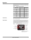
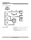
LED Status Indicators The diagnostic display panel shows the status of the SPD module with
diagnostically controlled green/red LEDs. If a unit is operating correctly, all the
phase LEDs will be illuminated green. To test the integrity of the diagnostics for
each phase, push the button below the phase LEDs on the diagnostic display
panel. The green LED will turn red and the alarm will sound, if the alarm is
enabled. Releasing the test button will complete the test; the red LED will turn
green and the alarm will shut off.
If an inoperable condition occurs on any phase, the audible alarm sounds and
the corresponding phase LED on the diagnostic display panel is illuminated red.
This indicates that the device needs service by qualified electrical personnel.
The audible alarm can be silenced by pressing the alarm enable/disable button.
The alarm will silence and the green alarm LED will not be lit. The red phase
LED will continue to be illuminated until the inoperative condition had been
cleared.
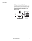
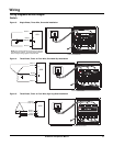
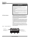
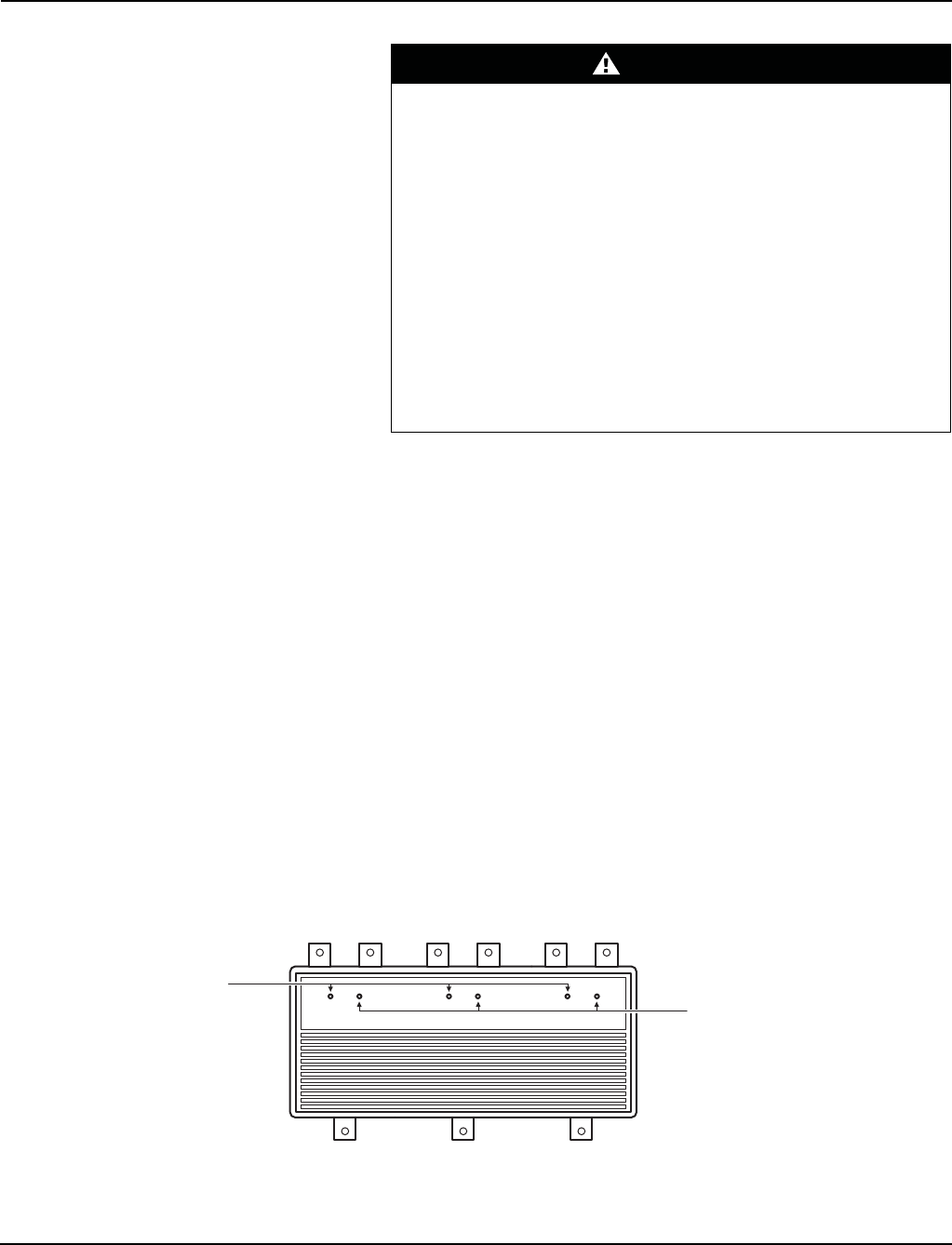
On an SurgeArrest
®
module (see Figure 6), if the left green LED is not lit, it
indicates a loss of suppression from line-to-ground for that phase. If the right
green LED is not lit, it indicates a loss of suppression from line-to-neutral for that
phase. If the diagnostic display has power and both green LEDs are not lit the
module should be replaced.
DANGER
HAZARD OF ELECTRIC SHOCK, EXPLOSION, OR ARC FLASH
• Apply appropriate personal protective equipment (PPE) and follow safe
electrical work practices. See NFPA 70E.
• This equipment must only be installed and serviced by qualified
electrical personnel.
• Turn off all power supplying this equipment before working on or inside
equipment.
• Always use a properly rated voltage sensing device to confirm power is off.
• Replace all devices, doors and covers before turning on power to this
equipment.
• This equipment must be effectively grounded per all applicable codes.
Use an equipment-grounding conductor to connect this equipment to
the power system ground.
Failure to follow these instructions will result in death or serious injury.
Figure 6: SurgeArrest
®
Module LEDs
GN N NGG
Left green LED lit:
L-G suppression is operating
Left green LED not lit:
Loss of surge suppression from L-G
Right green LED lit:
L-N suppression is operating
Right green LED not lit:
Loss of surge suppression from L-N
AØ BØ CØ
Operation