


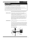
Prior to mounting the SPD, verify that the device has the same voltage
rating as the power distribution system in which it is installed by comparing
the nameplate voltage or model number on the SPD with the nameplate of
the electrical distribution equipment.
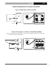
The specifier or user of the device should be familiar with the configuration
and arrangement of the power distribution system in which any SPD is to
be installed. The system configuration of any power distribution system is
based strictly on how the secondary windings of the transformer supplying
the service entrance main or load are configured. This includes whether
or not the transformer windings are referenced to earth via a grounding
conductor. The system configuration is not based on how any specific load
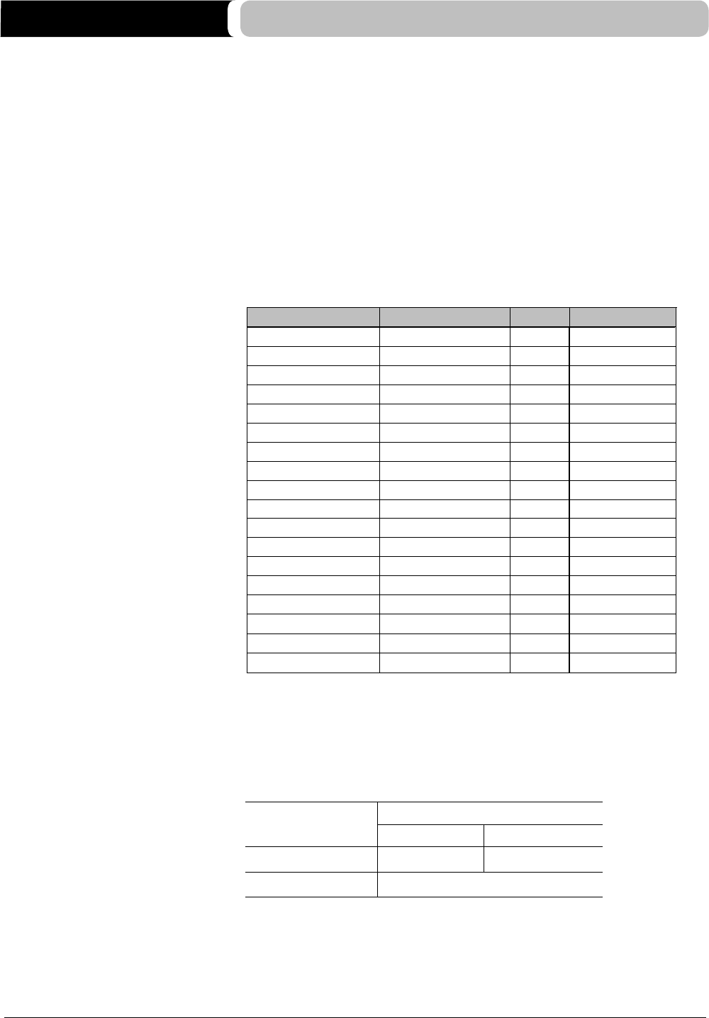
or equipment is connected to a particular power distribution system. See
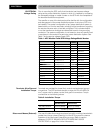
Table 1 for the service voltage of each SPD.
Table 1: APC Modular Panel SPD Voltage Ratings/Model Number
ELECTRICAL
Voltage Rating
S
ervice voltage configuration
1
20/208 wye 3Ph. Wye 4-wire +G
3Ph. Wye 4-wire +G
3Ph. Wye 4-wire +G
220/380 wye
PMF3S-A
PMF3DS-A
PMP3S-A
PMP3DS-A
PMG3S-A
PMG3DS-A
PML3S-A
PML3DS-A
120kA
120kA
120kA
120kA
120kA
120kA
120kA
120kA
PMF4S-A
PMF4DS-A
PMP4S-A
PMP4DS-A
PMG4S-A
PMG4DS-A
PML4S-A
PML4DS-A
1
20/208 wye
120/240 wye (Single Phase)
120/240 wye (Single Phase)
1Ph. Wye 3-wire +G
1Ph. Wye 3-wire +G
277/480 wye
277/480 wye
347/600 wye
347/600 wye
3Ph. Wye 4-wire +G
3Ph. Wye 4-wire +G
3Ph. Wye 4-wire +G
PMH4DSLM-A
120/208 wye
120/208 wye
120/240 wye (Single Phase)
120/240 wye (Single Phase)
277/480 wye
277/480 wye
347/600 wye
347/600 wye
3Ph. Wye 4-wire +G
3Ph. Wye 4-wire +G
3Ph. Wye 4-wire +G
1Ph. Wye 3-wire +G
1Ph. Wye 3-wire +G
3Ph. Wye 4-wire +G
3Ph. Wye 4-wire +G
3Ph. Wye 4-wire +G
3Ph. Wye 4-wire +G
160kA
160kA
160kA
160kA
160kA
160kA
160kA
160kA
160kA
MoDe
l nuMBer
ka rating
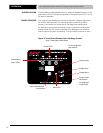
T
erminals are provided for phase (line), neutral, and equipment ground
connections. The SPD terminals accept a range of #12 to #2 AWG (34
mm
2
) c
opper wire for phase, neutral, and ground connectors. Torque
connections to the following values.
Table 2: Installation Torque
P
ower Connection Terminal Torque
W/O Disconnect W/ Disconnect
A
Ø, BØ, CØ & N 35 lb-in (4N·M) 50 lb-in (5.7N·M)
Ground 50 lb-in (5.7N·M)
The use of fusible disconnects requires a fuse with a melting characteristic
greater than the per phase (Clearing) I
2
t o
f the SPD to prevent nuisance
operation of the disconnect fuses during a surge. (Refer to caution
statement “LOSS OF BRANCH CIRCUIT POWER AND SURGE
PROTECTION” on page 2 for further information)
Terminals, Wire Size and
Installation Torque
Disconnect Means (External)
ELECTRICAL
APC MODULAR PANEL PRODUCTS Surge Protective Device (SPD)
8
PML-4Y-DC-DL-A
347/600 wye
3Ph. Wye 4-wire +G
160kA
*
*
Redundant 160kA system