


Installation and Operation Manual 17
When power is applied to the SPD and one or more of the diagnostic display
panel LEDs are red, and one or more module LEDs are out, the module should
be replaced. Refer to “Maintenance and Troubleshooting” on page 19 for proper
troubleshooting procedures.
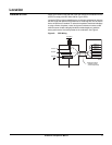
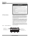
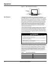
Audible Alarm Push the alarm enable/disable button to enable or disable the alarm (see
Figure 7). If the green alarm LED is lit the alarm is enabled. If the green alarm
LED is not lit the alarm is disabled.
Surge Counter The surge counter displays the number of transient voltage surges since the
counter was last reset. The counter is battery powered to retain memory in the
event of a power loss to the diagnostic display panel. To reset the surge counter
remove all power and press the small switch located inside the unit on the
underside of the diagnostic circuit board near the RJ45 connectors (also refer to
Figure 8). This will reset the counter to zero.
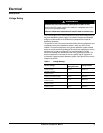
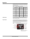
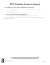
Table 4: SurgeArrest
®
Replacement Modules
System Voltage
Peak Surge Current
Rating (kA)
Catalog Numbers
120/240,
1-phase,
2-3 wire
120 BMP3-B
120/208Y, 127/220Y
3-phase,
3-4 wire
120 BMF3-B
240/120,
3-phase, 4-wire,
high-leg delta
120 BMJ3-B
277/480Y,
3-phase,
3-4 wire
120 BMG3-B
220/380Y, 230/400Y, 240/415Y
3 phase,
3-4 wire
120 BMH3-B
347/600Y,
3-phase,
3-4 wire
120 BML3-B
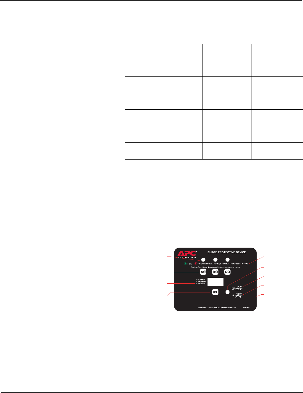
Figure 7: Three-Phase Diagnostic Display Panel with Surge Counter
NOTE: Phase B is not present on
single-phase applications
Alarm enable/disable
push button
Phase LEDs
On-Line diagnostics
push buttons
Surge counter
Surge counter
reset switch
or diagnostic
circuit board
Description of
phase LEDs
Alarm LED
Enable alarm
Disable alarm
Operation