


Replacing the Battery
This UPS has an easy to replace hot-swappable battery. Battery replacement is a safe procedure, isolated from electrical hazards. You may leave the UPS and loads on for the following procedure. See your dealer or call the
number in this manual for information on replacement battery kits.
Note: Please read the cautions in the APC Safety Guide.
Once the battery is disconnected, the loads are not protected from power outages.
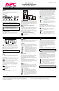
Battery Replacement Procedure - 2200 - 3000 VA Models
1. Grasp the top edge of the bottom front cover and tilt it out.
2. Unhook the bottom section of the front cover from the chassis and set it aside.
3. Use a flat-blade screwdriver or a coin to remove the two battery door screws and
open the door.
4. Grip the wires for the front set of batteries and pull firmly to disconnect the
connector from the battery compartment. Remove the batteries.
5. Pull the white cord on the front battery connector to remove the batteries.
6. Set aside the foam spacer located between the batteries.
7. Reach into the battery compartment and grasp the white cord on the other battery
connector. Pull firmly to disconnect the connector and remove the second set of
batteries.
Note: Be careful removing the batteries - they are heavy.
8. Slide the first set of new batteries into the unit. Hold the connector down below
the top of the batteries and toward the door, otherwise the assembly will not fit.
Guide the connector over the top of the batteries and press firmly to connect it to
the rear connector of the battery compartment.
9. Set the foam spacer against the rear batteries to prevent the wires from being
pinched.
Note: Small sparks at the battery connectors are normal during connection.
10. Slide the second set of batteries in, then guide the connector over the batteries
and press firmly to connect it to the front connector of the battery compartment.
11. Now close the battery door, replace the screws, and replace the lower front cover.
12. Dispose of the old battery properly at an appropriate recycling facility or return it
to the supplier in the packing material for the new battery. See the new battery
instructions for more information.
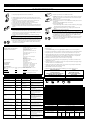
Battery Replacement Procedure - 450 - 1400 VA Models
1. Grasp the top of the front cover and tilt it out and down.
2. Unhook the bottom of the cover from the chassis and lift it upward to expose the
battery door. Be careful not to strain the ribbon cable. Do not touch the exposed
printed circuit board.
3. Fold the front cover on top of the UPS as shown.
4. Use a flat-blade screwdriver or a coin to remove the two battery door screws and
open the door.
Grasp the tab and gently pull the battery out of the UPS.
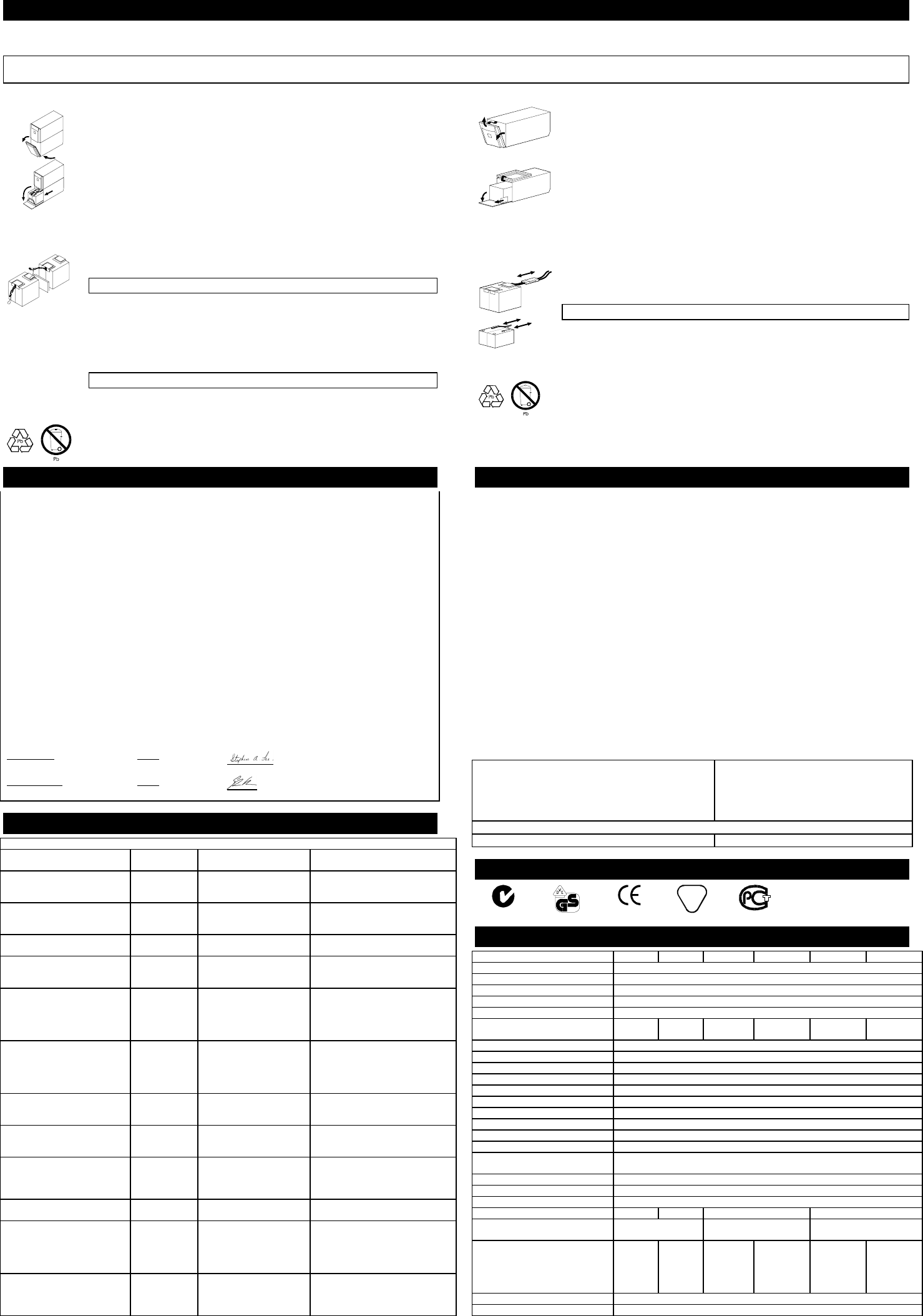
1400 VA
450 - 1000 VA
5. Disconnect the battery leads.
• For the 450 through 1000 VA models, loosen the connectors by gently wiggling
them while pulling straight back from the battery connector.
• For the 1400 VA model, pull the two gray couplers apart to disconnect the
battery.
6. Connect the battery leads to the new battery.
Note: Small sparks at the battery connectors are normal during connection.
• For the 450 through 1000 VA models, connect the red wire to the positive (+)
terminal and the black wire to the negative (–) terminal.
• For the 1400 VA model, connect the gray battery coupler to the UPS’s coupler.
7. Now slide the battery into the UPS, close the battery door, replace the battery
compartment screws, and replace the front cover.
8. Dispose of the old battery properly at an appropriate recycling facility or return it
to the supplier in the packing material for the new battery. See the new battery
instructions for more information.
Declaration of Conformity
Application of Council Directives:
89/336/EEC,73/23/EEC,92/31/EEC,
93/68/EEC,91/157/EEC
Standards to Which Conformity Declared:
EN55022, EN50082-1, EN50091, EN60950
Manufacturer's Name and Address:
American Power Conversion
132 Fairgrounds Road
West Kingston, Rhode Island, 02892, USA
-or-
American Power Conversion (A. P. C.) b. v.
Ballybritt Business Park
Galway, Ireland
-or-
American Power Conversion Phillipines
Second Street
Caivte EPZA
Roserio, Cavite Phillipines
Importer's Name and Address:
American Power Conversion (A. P. C.) b. v.
Ballybritt Business Park
Galway, Ireland
Type of Equipment:
Uninterruptible Power Supply
Model Numbers:
Smart-UPS 450, 700, 1000, 1400, 2200, 3000
Serial Numbers:
X9601 000 0000 — X9699 999 9999*
X9701 000 0000 — X9799 999 9999*
Years of Manufacture:
1995, 1996, 1997, 1998, 1999, 2000
Note:
Where X = B, O, W, or D
We, the undersigned, hereby declare that the equipment specified above conforms to the above directives.
Billerica, MA 1/1/97
Place Date Stephen A. Lee, Regulatory Compliance Engineer
Galway, Ireland 1/1/97
Place Date Gerard Rutten, Managing Director, Europe
User Configuration Items
Note: Setting these items requires optional software or hardware.
Function Factory
Default
User Selectable Choices Description
Automatic Self-Test Every 14 days
(336 hours)
Every 7 days (168 hours),
On Startup Only, No Self-
Test
Sets the interval at which the UPS
will execute a self-test.
UPS ID UPS_IDEN Up to eight characters to
define the UPS.
Use this field to uniquely identify the
UPS for network management
purposes.
Date of Last Battery
Replacement
Manufacture
Date
Date of Battery
Replacement
Reset this date on battery
replacement.
Minimum Capacity Before
Return from Shutdown
0 percent 15, 50, 90 percent The UPS will charge its batteries to
the specified percentage before return
from a shutdown.
Sensitivity Normal Reduced, Low Set lower than normal sensitivity to
avoid lowered battery capacity and
service life in situations where the
load can tolerate minor power
disturbances.
Duration of Low Battery
Warning
2 minutes 5, 7, 10 minutes Sets the time before shutdown at
which the UPS issues a low battery
warning. Set higher than the default
only if the OS needs the time for
graceful shutdown.
Alarm Delay After Line Fail 5 second delay 30 second delay, At Low
Battery Condition, No
Alarm
To avoid alarms for minor power
glitches, set the alarm delay.
Shutdown Delay 20 seconds 180, 300, 600 seconds Sets the interval between when the
UPS receives a shutdown command
and when shutdown occurs.
Synchronized Turn-on Delay 0 seconds 60, 180, 300 seconds To avoid branch circuit overload,
the UPS will wait the specified time
after the return of utility power before
turn-on.
Output Voltage 230 Vac 220, 225, 240 VAC Sets the output voltage for on-battery
operation.
High Transfer Point 253 Vac 264, 271, 280 VAC To avoid unnecessary battery usage,
set the High Transfer Point higher if
the utility voltage is chronically high
and the load is known to work well
under this condition.
Low Transfer Point 196 Vac 188, 204, 208 VAC Set the Low Transfer Point lower if
the utility voltage is chronically low
and the load can tolerate this
condition.
Service
If the UPS requires service do not return it to the dealer!
Follow these steps:
1. Use the Troubleshooting section of the Quick Reference Guide to eliminate common problems.
2. Verify that no circuit breakers are tripped. A tripped circuit breaker is the most common UPS problem!
3. If the problem persists, call customer service or visit the APC Internet Website (www.apcc.com).
• Note the model number of the UPS, the serial number, and the date purchased. A technician will ask
you to describe the problem and try to solve it over the phone, if possible. If this is not possible the
technician will issue a Return Merchandise Authorization Number (RMA#).
• If the UPS is under warranty, repairs are free. If not, there is a repair charge.
4. Pack the UPS in its original packaging. If the original packing is not available, ask customer service
about obtaining a new set.
• Pack the UPS properly to avoid damage in transit. Never use Styrofoam beads for packaging. Damage
sustained in transit is not covered under warranty.
• Include a letter with your name, RMA#, address, copy of the sales receipt, description of the trouble,
your daytime phone number, and a check (if necessary).
5. Mark the RMA# on the outside of the package
6. Return the UPS by insured, prepaid carrier to the address given to you by Customer Service.
North & Latin America Europe
APC APC
132 Fairgrounds Road Ballybritt Business Park
West Kingston, Rhode Island 02892 USA Galway, Ireland 10800-702000
1-800-800-4APC/1-401-789-5735 353-91-702020
Internet: http://www.apcc.com
E-Mail: apctech@apcc.com E-Mail: apceurtech@apcc.com
Regulatory Agency Approvals
N 39
4
B
ME 61
Specifications
450 VA 700 VA 1000 VA 1400 VA 2200 VA 3000 VA
Acceptable input voltage 0 - 325 VAC
Output voltage 196-253 VAC (by default)
Input Protection Resettable circuit breaker
Frequency limits (on-line operation) 50 or 60 Hz, ±5%
Transfer time 2 ms typical, 4 ms maximum
Maximum load 450 VA
280 W
700 VA
450 W
1000 VA
670 W
1400 VA
950 W
2200 VA
1600 W
3000 VA
2250 W
On-battery output voltage 220, 225, 230, or 240 VAC
On-battery frequency 50 or 60 Hz, ±0.1 Hz; unless synchronized to utility during brownout.
On-battery waveshape Low-distortion sine wave
Protection Overcurrent and short-circuit protected, latching shutdown on overload.
Noise Filter Normal and common mode EMI/RFI suppression, 100 kHz to 10 MHz
Battery type Spill proof, maintenance free, sealed lead-acid
Typical battery life 3 to 6 years, depending on number of discharge cycles and ambient temperature
Typical recharge time 2 to 5 hours from total discharge
Operating temperature 0 to +40 ºC (+32 to +104 ºF)
Storage temperature -15 to +45 ºC (+5 to +113 ºF)
Operating and storage relative
humidity
0 to 95%, non-condensing
Operating elevation 0 to +3,000 m (0 to +10,000 ft)
Storage elevation 0 to +15,000 m (0 to +50,000 ft)
Electromagnetic immunity IEC 61000-2, 61000-3, 61000-4
Audible noise in dBA at 1 m (3 ft) <41 <42 <45 <53
Size (H x W x D) 15.8 x 13.7 x 35.8 cm
(6.2 x 5.4 x 14.1 in.)
21.6 x 17 x 43.9 cm (8.5 x
6.7 x 17.3 in.)
43.2 x 19.6 x 54.6 cm (17.0
x 7.7 x 21.5 in.)
Weight - net (shipping) 10.5
(11.8)
kg
23.2
(26) lb.
13.1
(14.5)
kg
29 (32)
lb.
18.8
(20.8) kg
41.5 (46)
lb.
24.1 (26.1)
kg
53 (58) lb.
51 (60.8) kg
112 (134)
lb.
55.8 (64.4)
kg
123 (142)
lb.
Safety approvals GS licensed by VDE to EN 50091 and 60950
EMC verification CISPR 22 Class A