


990-0253A, Revision 2 6/99 4
Install the Rails
Note:
The mounting rails are only necessary if you are using a four-post rack. If you are using a two-post
rack the Redundant Switch will be mounted by the ears alone. Skip to Connect and Route the
Cables.
Two rails and associated hardware are included with the Redundant Switch. For information on which clips
and screws the rack you are using requires, see Appendix A: Rack Mount Supplement. Prepare the rack’s
rail-holes to mount the Redundant Switch’s ears and rails as appropriate.
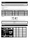
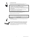
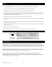
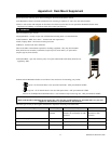
The rails are adjustable and can be disassembled by removing the slide screw and nut, shown at •,
above. Disassemble the rails. Set the screws, nuts, and the front segments, •, aside.
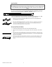
1. Mount the ears of the rear rail segments, Ž, to the rear rack rails on the prepared rack
using appropriate rack hardware.
2. The sides of the Redundant Switch have two holes at the rear. Align the top two holes on
the front rail segment, •, with the two holes at the rear of the Redundant Switch and
secure them with the tapered head screws provided.
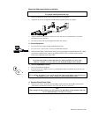
Connect and Route the Cables
3. Connect the communication cables to the front of the Redundant Switch.
4. If the accessories and options you are using require front cable connections, connect these
also.
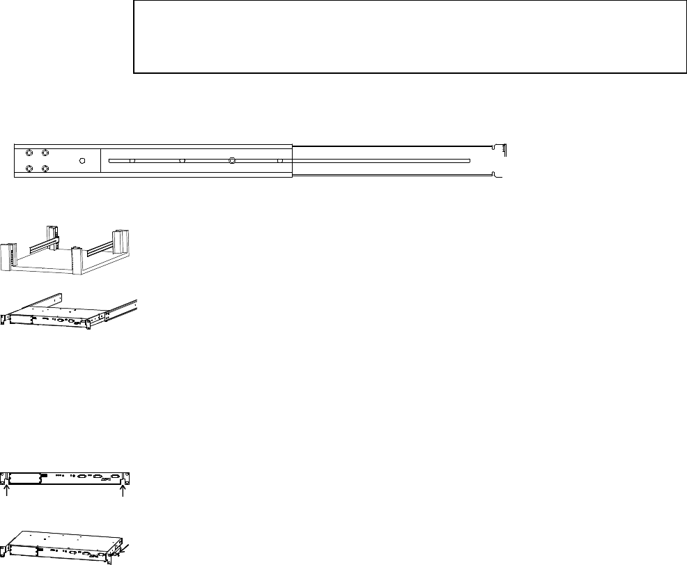
5. Route the cables around the Redundant Switch using the side channels, so that they can be
connected to the appropriate equipment mounted in the rack. Arrows in the adjacent figure
indicate the side channels.
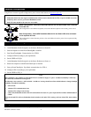
6. Install one or both of the enclosed plastic twist locks to secure the cables, if desired. The
arrow in the adjacent figure shows one twist lock mounted to the side of the Redundant
Switch.
•
Ž
•