


990-3239A 07/2008
Installation Guide Smart-UPS I/O Hardwire Kit
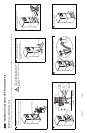
Connect the terminal block and UPS connectors as shown in diagram.
A
C Input Connector
A
C Input
Connectors
AC Input
Connector
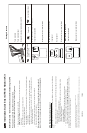
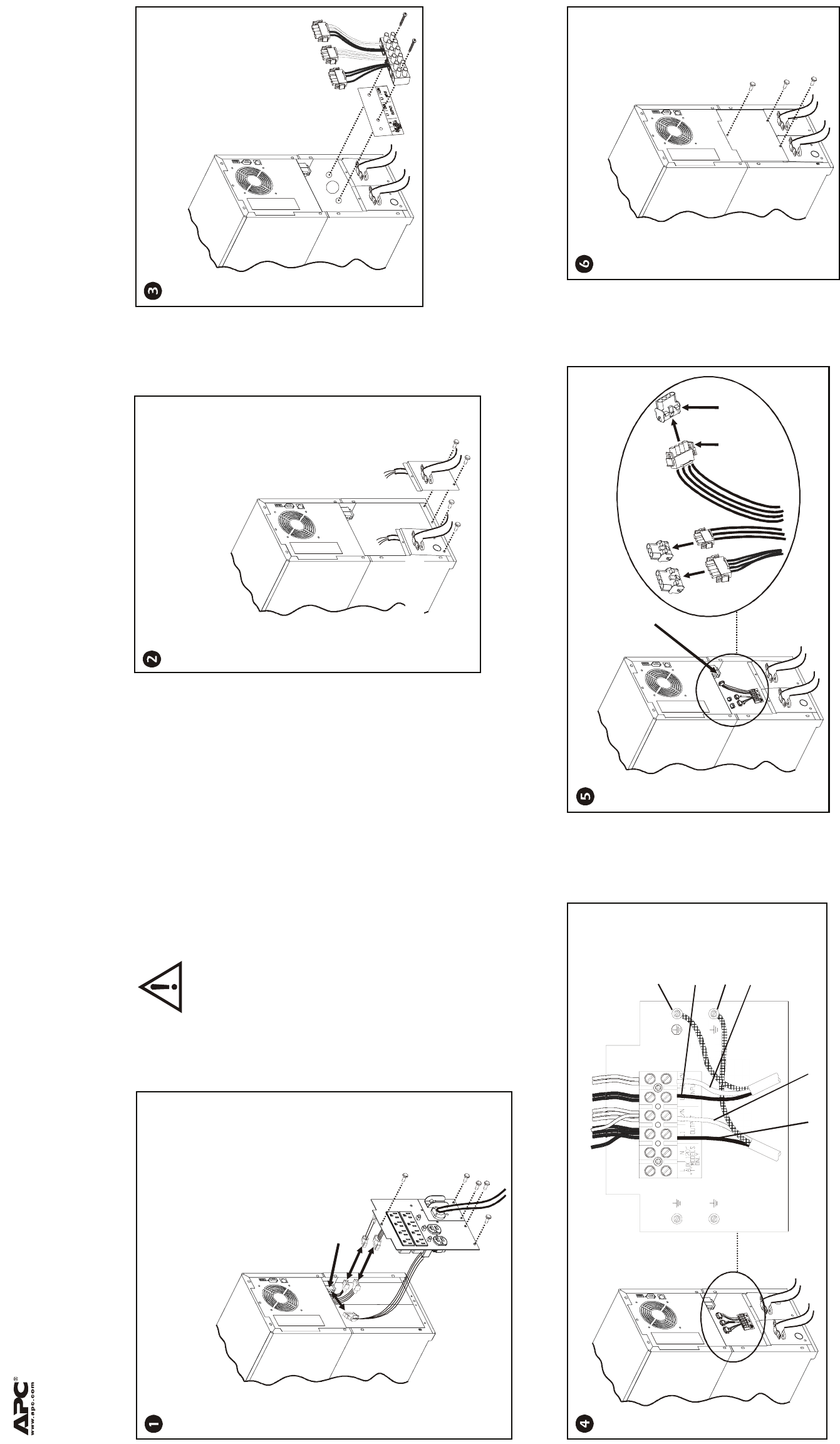
Remove the five screws that secure the PDU/IO panels
to the UPS.
Save these screws for securing the I/O hardwire panels.
Disconnect the PDU/IO cables as shown in the diagram.
NOTE: The input and output cables may be
connected to the terminal block prior to
installing the panels and the terminal block
in the UPS.
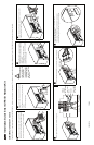
2200/3000 Tower 100/120/230 V models
The AC input/output panels on the 2200/3000 VA tower units vary in appearance. The hardwire panels and hardwiring configurations for the 2200/3000 VA tower units are identical.
Secure the terminal block and label to the
UPS as shown in the diagram, using
two screws (supplied).
Secure the hardwire input and output panels
(supplied), to the UPS using four of the screws
removed from the PDU/IO panels.
Install appropriate strain relief clamps
(not supplied), to the I/O panels as shown in
the diagram.
Connect input and output wires as shown in diagram.
Secure the blank panel to the UPS using
three screws (supplied).
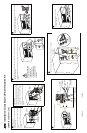
Primary
Ground
(Green Wire)
Ground
Input Line1
(Hot)
Output Line1
Input Line2
(or Neutral)
Output Line2
(or Neutral)
Output panel
Input panel