


8
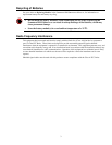
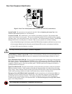
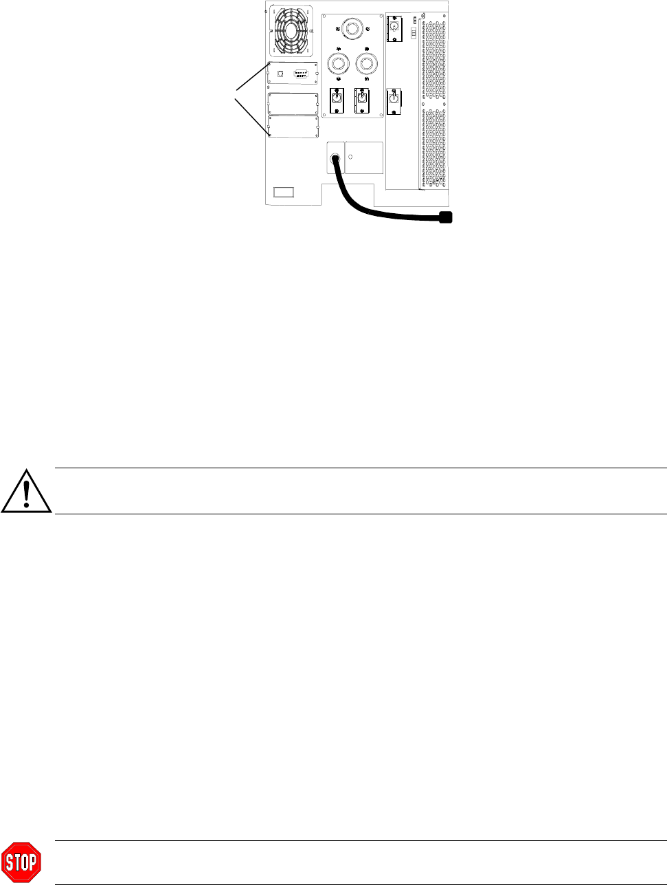
Rear View Component Identification
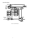
Figure 3: Rear View of the Symmetra RM (200/208 Vac / L1-L2-G version shown)
System Fan : The system fan can be replaced in the field. Refer to Replacing the System Fan, in the
S
YMMETRA RM OPERATION MANUAL, for instructions.
Accessory Ports : APC manufactures a set of auxiliary user interface accessories. The Symmetra RM
contains a total of three accessory ports. The top slot is preloaded with the SYCC card that provides computer
and battery ports. Two unoccupied accessory slots is provided. The Symmetra RM also includes a Web/SNMP
Management Card for accessing data via a network. Other accessory options are available, including:
• Out-of-Band Monitoring Card (formerly named CallUPS) initiates telephone notification of power event
• Environmental Monitoring Card (formerly named MeasureUPS) monitors environmental conditions
• Control-UPS control and monitor via modem
Use only accessory devices labeled “Symmetra compatible.”
External Battery Cabinet Connector : Connect an External Battery Cabinet to the Symmetra RM using
this connector. The Symmetra RM can connect to a maximum of seven external battery cabinets in a daisy-
chain fashion.
Power Distribution Panel (PDU) : The type of power panel depends on the voltage range of the Symmetra
RM. Figure 3 shows a Symmetra RM with a 200/208 Vac (L1-L2-G) power panel. It contains one L6-30 and
two L6-20 receptacles. The 220/230/240 Vac (L1-N-G) power panel contains eight IEC C13 and two IEC C19
receptacles. Figure 8, page 16, shows the two PDU panels. The PDU panel can be changed in the field by a
qualified technician or electrician.
Input Circuit Breaker : The input circuit breaker, located at the back of the frame, protects the Symmetra
RM from extreme overloads. When switched to Stand By the Symmetra RM is disconnected from incoming
utility voltage. When switched to the On position, power flows from the utility source into the Symmetra RM.
Under normal operating conditions, the input circuit breaker always remains in the On position.
Emergency Power Off (EPO) Switch Connection : Use this connection to wire the Symmetra RM to an
emergency power off switch located away from the unit. This switch shuts off power to Symmetra RM and
prevents the unit from operating on-battery. The terminal connections for the EPO switch are physically
isolated from the primary circuitry of the Symmetra RM. See Wire the Emergency Power Off (EPO) Switch,
page 14, for wiring instructions.
EPO wiring must be installed by a qualified electrician only.