


9
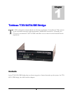
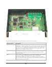
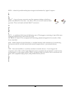
The following table describes each of the elements shown in the above picture.
Internal Element
Description
1394B (FireWire 800)
The T35i must be connected to the host computer via a
FireWire800/1394B connection. This is the interface through which each of
the T35i's two I/O channels will communicate with the host computer. It is
acceptable to use FireWire400/1394A instead (with an appropriate cable
adapter), but performance will be reduced.
DIP Switch Bank
The T35i has one DIP switch bank with four switches. The next section in
this document, Configuration Switches, describes the function of these
switches in detail.
Power
Power should be provided to the T35i through the standard 4-pin "Molex"-
style power connector shown in the picture. The T35i requires
approximately 450mA @ +5VDC for its internal operation. This figure
does not include the power requirements of the hard disk connected to the
DC OUT connector on the T35i.