1
5
610
11
15
1
2
3
4
5
6
7
8
12
34
15 HIGH DENSITY DSUB
FEMALE
1 Analog R IN
2 Analog G IN
3 Analog B IN
4 AGND
5 AGND
6 Analog R GND IN
7 Analog G GND IN
8 Analog B GND IN
9 Reserved
10 Sync GND IN
11 AGND
12 DDC/SDA
13 HSync IN
14 VSync IN
15 DDC/SCL
8 PIN MINIDIN
FEMALE
1 Mac ADB
2 PS/2 clock
3 PS/2 data
4 RS232 TXD
5 Not used
6 RS 232 RXD
7 RS 232 CTS
8 GND
4 PIN MINIDIN
FEMALE
1 GND
2 GND
3 Luma
4 Common
3.5 mm
JACK
TIP: right
RING: left
STEM: common
PHONO/RCA
FEMALE
STEM: composite
SHIELD: GND
DIGITAL
USB
CONNECTORS
ANSCHLÜSSE CONNECTEURS CONECTORES CONNETORI KONTAKTER
12
3 4
1 VCC
2 - Data
3 +Data
4 GND
L
FCC STATEMENT
This equipment complies with the limits for a Class A comput
ing device, pursuant to Subpart J of Part 15 of FCC rules. Only peripherals (computer input/output
devices, terminals, printers, etc.) certified to comply with the Class A limits may be attached to a computer that complies with Class A limits. When connecting to a
peripheral device, a shielded input/output cable is required to ensure compliance with FCC rules. The shielded cable that must be used is supplied with the
equipment. Operation with non-certified peripherals or non-shielded cables is likely to result in interference to radio and TV reception.
This equipment generates and uses radio-frequency energy and
, if not installed and used in accordance with the instruction manual, may cause interference to radio
and television reception. It has been tested and found to comply with the limits for a Class A computing device in accordance with the specifications in Subpart J of
Part 15 of the FCC rules, which are designed to provide reasonable protection against such interference when operated in a commercial environment. However,
there is no guarantee that interference will not occur in a particular installation. If this equipment does cause interference to radio or television reception, which can be
determined by turning the equipment off and on, the user is encouraged to try to correct the interference by one or more of the following measures:
· Reorient the receiving antenna.
· Relocate the projector with respect to the receiver.
· Plug the equipment to a different outlet so that equipment
and receiver are on different branch circuits.
· Fasten cables using mounting screws to ensure adequate EMI control.
You may require the following booklet from the Federal Commu
nications Commission (FCC): "How to identify and resolve radio and TV interference problems",
available from the U.S. Government Printing Office, Washington, DC 20402, Stock No. 004-000-00345-4.
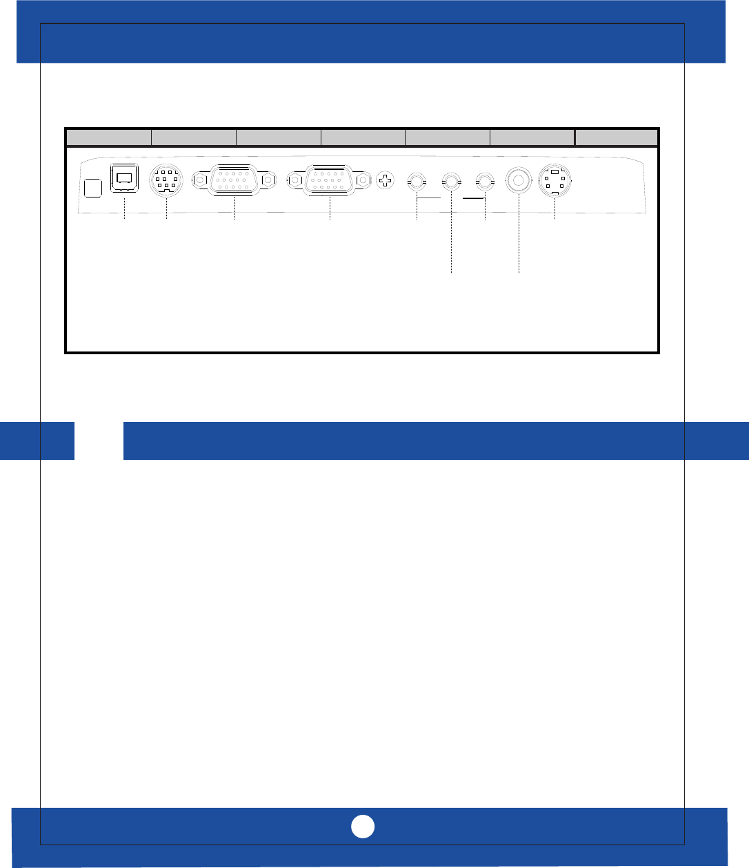
MOUSE 1
USB MOUSE 2
COMPUTER
AUDIO
LINE OUT
MONITOR
COMP IN
VIDEO IN
VIDEO
S-VIDEO
1
5
610
11
15
15 HIGH DENSITY DSUB
FEMALE
1 Analog R OUT
2 Analog G OUT
3 Analog B OUT
4 Reserved
5 AGND
6 Analog R GND OUT
7 Analog G GND OUT
8 Analog B GND OUT
9 Reserved
10 Sync GND OUT
11 Not used
12 DDC/SDA
13 HSync OUT
14 VSync OUT
15 DDC/SCL
3.5 mm
JACK
TIP: right
RING: left
STEM: common
3.5 mm
JACK
TIP: right
RING: left
STEM: common
www.askproxima.com
20
C2 COMPACT / C6 COMPACT
TECHNICAL DATA
TECHNISCHE DATEN CARACTERISTIQUES TECHNIQUES DATOS TÉCNICOS DATI TECNICI TEKNISKE DATA


