


Chapter 3 65
Main Unit Disassembly Process
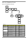
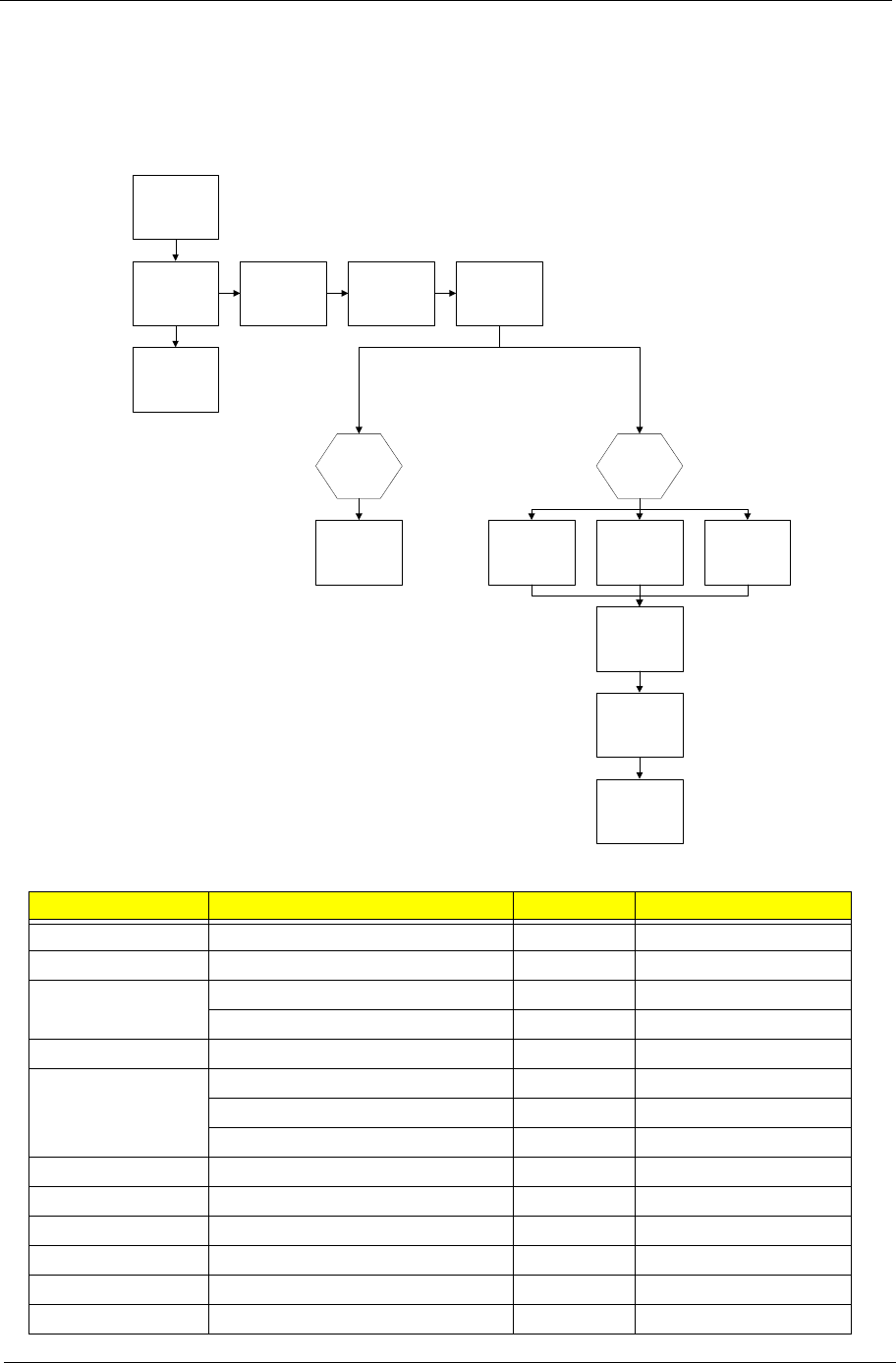
Main Unit Disassembly Flowchart
Screw List
Step Screw Quantity Part No.
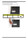
Switch Cover M2.5*6.5-I (BZN(NYLOK-RED) 10 86.ARE07.001
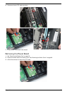
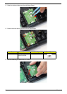
Power Board M2.0*3.0-I (BKAG) (NYLOK) IRON 3 86.ARE07.002
Speaker Module M3*3 (not available for order) 3 N/A
M2.5*4.0-I (NI)(NYLOK) 2 86.D01V7.001
LCD Module M2.5*5-I (BNI)(NYLOK) 4 86.A03V7.003
Upper Cover M2.0*3.0-I-NI-NYLOK 5 86.A08V7.005
M2.5*6.5-I (BZN(NYLOK-RED) 11 86.ARE07.001
M2.5*6.5-I (BZN(NYLOK-RED) 10 86.ARE07.001
F/P Reader M2.0*3.0-I-NI-NYLOK 3 86.A08V7.005
USB Board M2.0*3.0-I (BKAG) (NYLOK) IRON 1 86.ARE07.002
Modem Module M2.0*3.0-I-NI-NYLOK 2 86.A08V7.005
Bluetooth Module M2.0*3.0-I-NI-NYLOK 1 86.A08V7.005
Mainboard M2.5*4.0-I (NI)(NYLOK) 3 86.D01V7.001
Thermal Module M2.5*4.0-I (NI)(NYLOK) 2 86.D01V7.001
Remove External
Modules before
proceeding
Remove
Thermal Module
Remove
Mainboard
Remove
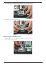
Power Board
Remove
Fingerprint
Reader
Remove
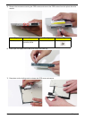
Switch Cover
Remove
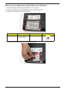
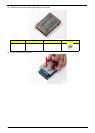
Keyboard
Remove
CPU
Remove
LCD Module
Remove
Bluetooth Module
Remove
Antenna
Remove
USB Board
Remove
Modem Module
Remove
Lower
Cover
Remove
Upper
Cover