


Chapter 3 53
External Module Disassembly Process
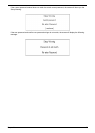
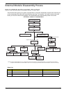
External Modules Disassembly Flowchart
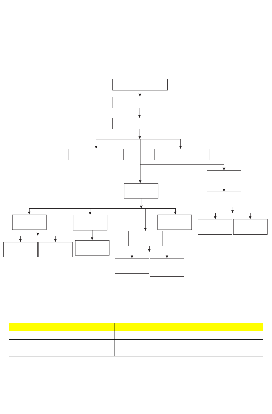
The flowchart below gives you a graphic representation on the entire disassembly sequence and instructs you
on the components that need to be removed during servicing. For example, if you want to remove the main
board, you must first remove the keyboard, then disassemble the inside assembly frame in that order.
Screw List
Item Screw Color Part No.
A M2 x L4 Black 86.00E34.738
B M2 x L4 Silver 86.9A552.4R0
D M3 x L3 Silver 86.00E78.643
EXTERNAL MODULE DISASSEMBLY
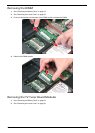
WLAN
BOARD
TURN OFF POWER
AND PERIPHERALS
UNPLUG POWER
CABLES
Bx1/Bx2*
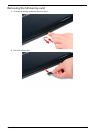
LOWER
COVER
Captive Screwx9
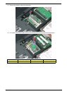
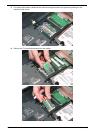
DIMM
MODULES
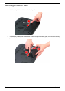
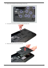
REMOVE BATTERY
PACK
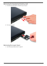
SD DUMMYCARD
ExpressCard
DUMMYCARD
Ax6
Bx2
ODD
MODULE
OPTICALDISK
DRIVE
OPTICAL
LOCKER
BRACKET
HDD 2
COVER
Captive Screwx2
Dx4
HDD 2
MODULE
HARD DISK
BRACKET
HARD DISK
DRIVE
Bx1
Dx4
HDD 2
MODULE
HARD DISK
BRACKET
HARD DISK
DRIVE
Bx1
Bx1
TVTUNER
BOARD
Bx2*
*Note:Aspire 8730/8730Z SeriesTV Tuner Board uses one screw (B).Aspire 8530 SeriesTVTuner Board use latches.
Aspire 8730/8730Z Series WLAN Board uses one screw (B).Aspire 8530 Series WLAN Board uses two screws (B).