


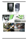


Chapter 5 63
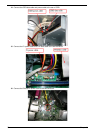
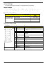
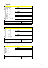
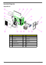
Front USB
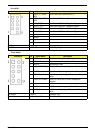
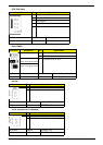
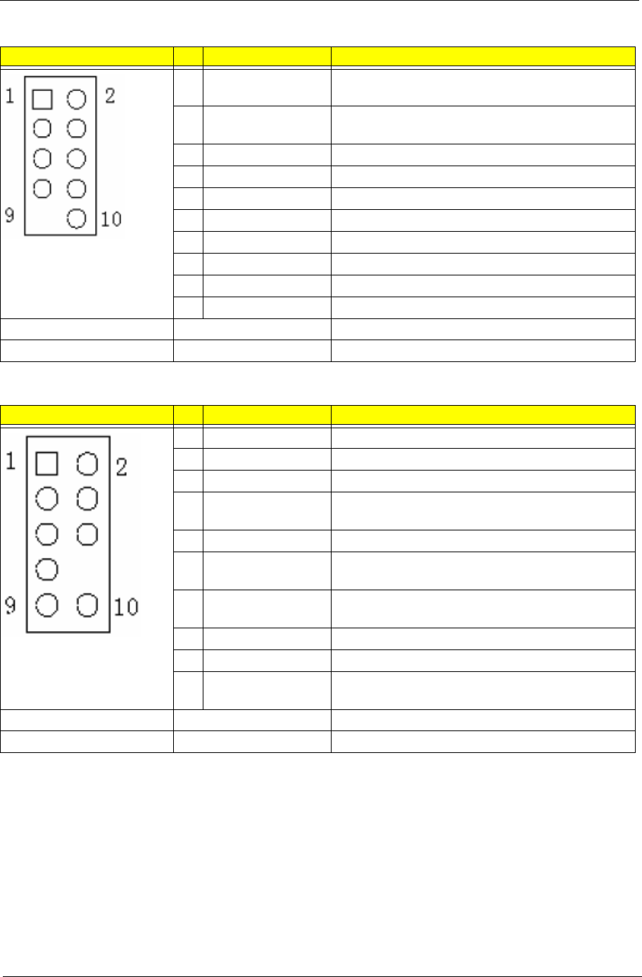
Front Audio
Illustration Pin Signal Name Description
1
VREG_FP_USBP
WR0
Front Panel USB Power(Ports 0,1)
2
VREG_FP_USBP
WR0
Front Panel USB Power(Ports 0,1)
3
USB_FP_P0- Front Panel USB Port 0 Negative Signal
4
USB_FP_P1- Front Panel USB Port 1 Negative Signal
5
USB_FP_P0+ Front Panel USB Port 0 Positive Signal
6
USB_FP_P1+ Front Panel USB Port 1 Positive Signal
7
Ground
8
Ground
9
Key
10
Ground
Silk Screen Footprint Schematic Part
F_USB? H2X5MZO9 HEADER_2X5_9
Illustration Pin Signal Name Description
1
MIC2-L Front Panel Microphone input signal
2
AUD_GND Ground used by Analog Audio Circuits
3
MIC2-R Microphone Power
4
AUD_PRESENCE_
L
Filtered +5V used by Analog Audio Circuits
5
LINE2-R Right Channel Audio signal to Front Panel
6
MIC2-JD Right Channel Audio signal Return from Front
Panel
7
FRONT-IO-SENSE RSVD for future use to control Headphone
Amplifier
8
Key
No Pin
9
LINE2-L Left Channel Audio signal to Front Panel
10
LINE2-JD Left Channel Audio signal Return from Front
Panel
Silk Screen Footprint Schematic Part
F_AUDIO
h2x5mzo8_1h86
HEADER_2X5_8