


ASUS P9X79 PRO 2-3
Chapter 2
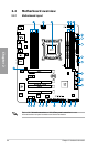
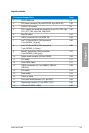
Layout contents
Connectors/Jumpers/Slots Page
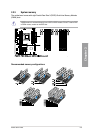
1. DDR3 DIMM slots 2-5
2. ATX power connectors (24-pin EATXPWR, 8-pin EATX12V) 2-32
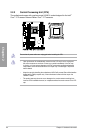
3. LGA2011 CPU socket 2-4
4. CPU, chassis, and power fan connectors (4-pin CPU_FAN, 4-pin
CPU_OPT_FAN, 4-pin CHA_FAN1/2/3/4)
2-30
5. MemOK! switch 2-16
6. USB 3.0 connector (20-1 pin USB3_56) 2-28
7. Intel
®
X79 Serial ATA 6.0 Gb/s connectors
(7-pin SATA6G_1/2 [gray])
2-25
8. Intel
®
X79 Serial ATA 3.0 Gb/s connectors
(7-pin SATA3G_3–6 [blue])
2-26
9. Marvell
®
Serial ATA 6.0 Gb/s connectors
(7-pin SATA6G_E1/E2 [gray])
2-27
10. System panel connector (20-8 pin PANEL) 2-33
11. TPU switch 2-17
12. Clear CMOS switch 2-17
13 USB 2.0 connectors (10-1 pin USB910, USB1112,
USB1314)
2-28
14. EPU switch 2-18
15. Reset switch 2-15
16. Power-on switch 2-15
17. Front panel audio connector (10-1 pin AAFP) 2-32
18. Digital audio connector (4-1 pin SPDIF_OUT) 2-29
19. Q-Code LED (LED1, LED2) 2-29