


1-14
Chapter 1: Product introduction
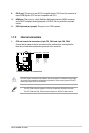
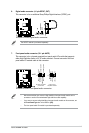
4. Line In port (light blue). This port connects to the tape, CD, DVD player, or other
audio sources.
5. Line Out port (lime). This port connects to a headphone or a speaker. In the 4, 6, and
8-channel congurations, the function of this port becomes Front Speaker Out.
6. Microphone port (pink). This port connects to a microphone.
Refer to the audio conguration table below for the function of the audio ports in 2, 4, 6, or
8-channel conguration.
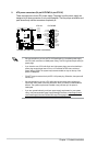
Audio 2, 4, 6, or 8-channel conguration
Port
Headset
2-channel
4-channel 6-channel 8-channel
Light Blue (Rear panel) Line In Rear Speaker Out Rear Speaker Out Rear Speaker Out
Lime (Rear panel) Line Out Front Speaker Out Front Speaker Out Front Speaker Out
Pink (Rear panel) Mic In Mic In
Bass/Center Bass/Center
Lime (Front panel)
— — — Side Speaker Out
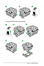
To congure an 8-channel audio output:
Use a chassis with HD audio module in the front panel to support an 8-channel audio
output.
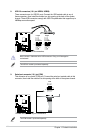
7. USB 2.0 ports 1 and 2. These two 4-pin Universal Serial Bus (USB) ports are for USB
2.0/1.1 devices.
8. USB 3.0 ports 1 and 2. These two 9-pin Universal Serial Bus (USB) ports are for USB
3.0 devices.
• DO NOT connect a keyboard / mouse to any USB 3.0 port when installing Windows
®
operating system.
• Due to USB 3.0 controller limitations, USB 3.0 devices can only be used under a
Windows
®
OS environment and after USB 3.0 driver installation.
• USB 3.0 devices can only be used for data storage.
• We strongly recommend that you connect USB 3.0 devices to USB 3.0 ports for faster
and better performance from your USB 3.0 devices.
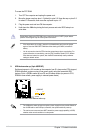
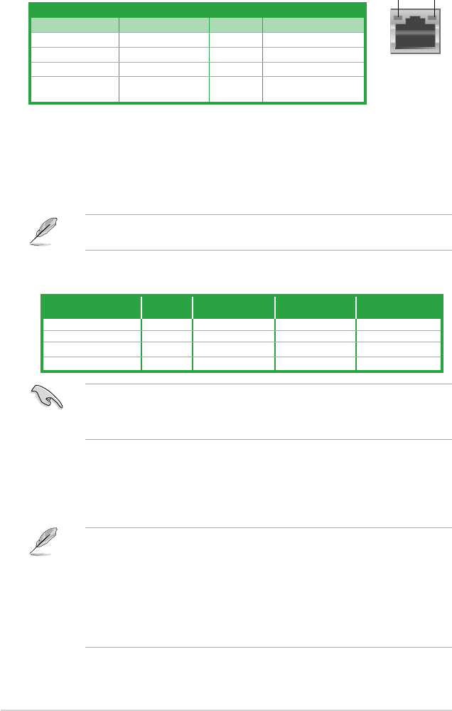
LAN port
SPEED
LED
ACT/LINK
LED
Activity/Link LED Speed LED
Status Description Status Description
Off No link OFF 10Mbps connection
Orange Linked ORANGE 100Mbps connection
Orange (Blinking) Data activity
GREEN 1Gbps connection
Orange (Blinking
then steady)
Ready to wake up
from S5 mode
LAN port LED indications