


ASUS B85M-G
1-19
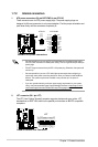
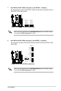
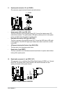
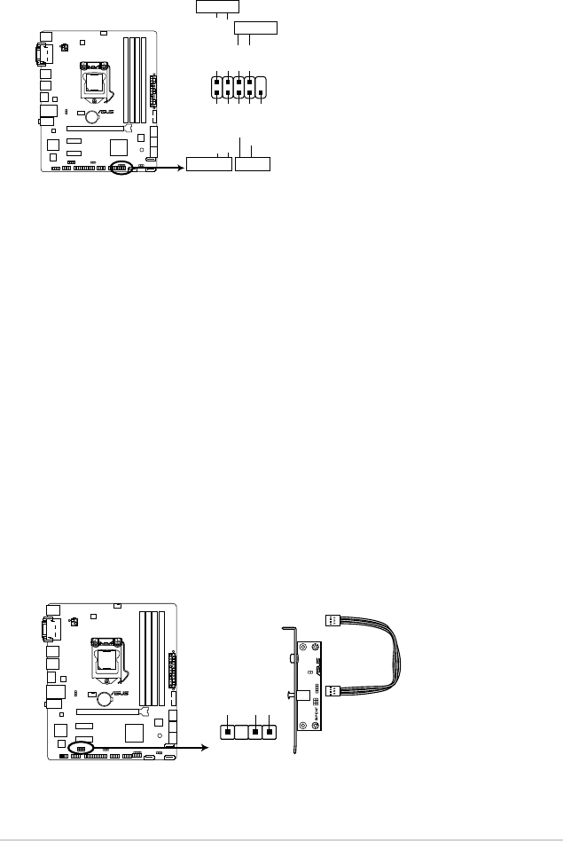
11. System panel connector (10-1 pin PANEL)
This connector supports several chassis-mounted functions.
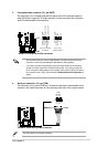
• System power LED (2-pin PWR_LED)
This 2-pin connector is for the system power LED. Connect the chassis power LED
cable to this connector. The system power LED lights up when you turn on the system
power, and blinks when the system is in sleep mode.
• Hard disk drive activity LED (2-pin HDD_LED)
This 2-pin connector is for the HDD Activity LED. Connect the HDD Activity LED cable
to this connector. The HDD LED lights up or ashes when data is read from or written
to the HDD.
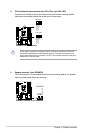
• ATX power button/soft-off button (2-pin PWR_BTN)
This connector is for the system power button.
• Reset button (2-pin RESET)
This 2-pin connector is for the chassis-mounted reset button for system reboot without
turning off the system power.
B85M-G
PIN 1
PWR BTN
PWR_LED+
PWR_LED-
PWR
GND
HDD_LED+
HDD_LED-
Ground
HWRST#
(NC)
F_PANEL
PWR_LED
+HDD_LED RESET
B85M-G System panel connector
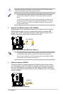
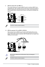
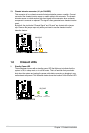
12. Digital audio connector (4-1 pin SPDIF_OUT)
This connector is for an additional Sony/Philips Digital Interface (S/PDIF) port. Connect
the S/PDIF Out module cable to this connector, then install the module to a slot
opening at the back of the system chassis.
SPDIF_OUT
+5V
SPDIFOUT
GND
B85M-G
B85M-G Digital audio connector