


ASUS C8HM70-I Series
1-3
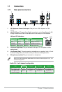
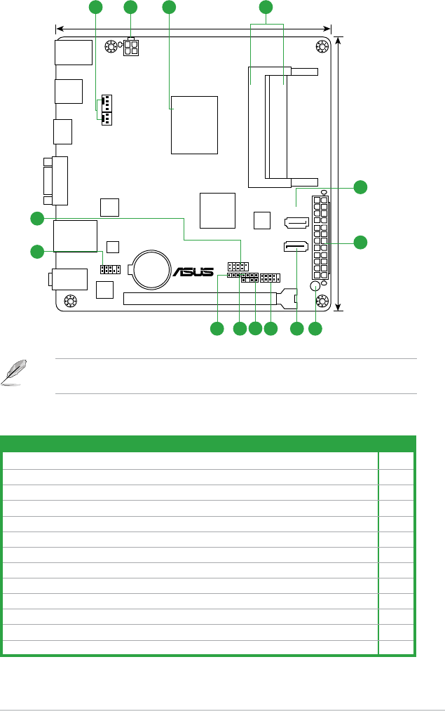
1.2.3 Motherboard layout
C8HM70-I/HDMI
USB1112
AAFP
Lithium Cell
CMOS Power
ALC
887
RTL
8111F
Super
I/O
64Mb
BIOS
SB_PWR
CLRTC
SPEAKER
CHASSIS
EATXPWR
ATX12V
Intel
®
HM70
Intel
®
Celeron847
DDR3 DIMM_B1 (64bit, 204-pin module)
DDR3 DIMM_A1 (64bit, 204-pin module)
SATA3G_1
SATA6G_1
KB_USB910
USB3_12
HDMI
AUDIO
LAN_USB34
F_PANEL
CHA_FAN
CPU_FAN
VGA
PCIEX16_1
17.0cm(6.7in)
17.0cm(6.7in)
4
2
5
13
12
11 7
6
10
9
8
21 3
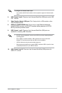
1.2.4 Layout contents
Connectors/Jumpers/Slots/LED Page
1. CPU and chassis fan connectors (3-pin CPU_FAN and 4-pin CHA_FAN) 1-12
2. ATX power connectors (24-pin EATXPWR, 4-pin ATX12V) 1-11
3. Intel
®
Celeron847 (BGA1023) processor 1-4
4. DDR3 SO-DIMM sockets 1-4
5. Serial ATA 6.0Gb/s connectors (7-pin SATA6G [gray]) 1-13
6. Standby power LED (SB_PWR) 1-1
7. Serial ATA 3.0Gb/s connectors (7-pin SATA3G [blue]) 1-13
8. System panel connector (10-1 pin PANEL) 1-14
9. Chassis intrusion connector (4-1 pin CHASSIS) 1-11
10. Speaker connector (4-pin SPEAKER) 1-14
11. Clear RTC RAM (3-pin CLRTC) 1-7
12. Front panel audio connector (10-1 pin AAFP) 1-10
13. USB 2.0 connectors (10-1 pin USB1112) 1-12
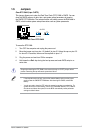
Following Intel’s specication, USB 2.0 ports 5 ~ 8 are disabled on the motherboards with
Intel
®
HM70 chipset.