


40 ASUS CUSL2 User’s Manual
Connectors
3. H/W SETUP
3. HARDWARE SETUP
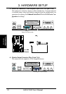
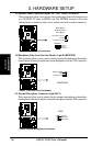
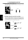
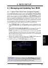
22) LCD-TV Headers (18-pin, 18-1 pin LCDTV)
These headers require an optional LCD module for LCD output or a TV-out
module for TV output.
CUSL2
®
CUSL2 LCD-TV Headers
1
LCDTV
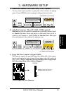
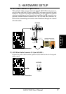
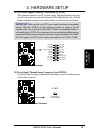
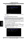
23) USB Headers (5-pin USB2, 10-1 pin USB47, 10-1 pin USB56)
If the USB Ports on the back panels are inadequate, three USB headers are avail-
able for five additional USB ports. Connect the 5-pin ribbon cable from the
provided 3-port USB connector set to the midboard 5-pin USB header and the
10-1 pin ribbon cable to one of the two midboard 10-1 pin USB headers and
mount the USB connector set to an open slot on your chassis.
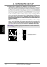
CUSL2 USB Headers
CUSL2
®
USB47
1
5
6
10
1: USB Power
2: USBP4–
3: USBP4+
4: GND
5: NC
6: USB Power
7: USBP7–
8: USBP7+
9: GND
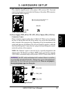
USB56
1
5
6
10
1: USB Power
2: USBP5–
3: USBP5+
4: GND
5: NC
6: USB Power
7: USBP6–
8: USBP6+
9: GND
USB2
1
USBPWR
USBP2-
USBP2+
GND