


1-15Chapter 1: Product introduction
• Do not forget to connect the fan cables to the fan connectors. Insufcient air ow inside
the system may damage the motherboard components. These are not jumpers! Do not
place jumper caps on the fan connectors!
• For system stability, ensure that you connect a chassis fan to the motherboard.
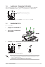
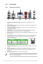
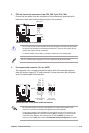
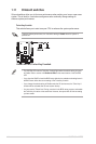
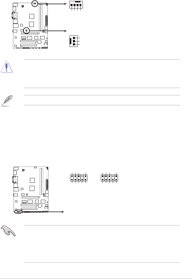
2. CPU and chassis fan connectors (4-pin CPU_FAN, 3-pin CHA_FAN)
Connect the fan cables to the fan connectors on the motherboard, ensuring that the
black wire of each cable matches the ground pin of the connector.
The CPU_FAN connector supports a CPU fan of maximum 2A (24 W) fan power.
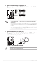
E45M1-M PRO
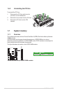
E45M1-M PRO fan connectors
CPU_FAN
CHA_FAN
CPU FAN PWM
CPU FAN IN
CPU FAN PWR
GND
GND
+12V
Rotation
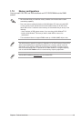
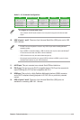
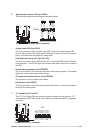
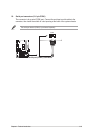
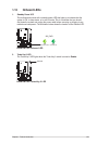
3. Front panel audio connector (10-1 pin AAFP)
This connector is for a chassis-mounted front panel audio I/O module that supports
either HD Audio or legacy AC`97 audio standard. Connect one end of the front panel
audio I/O module cable to this connector.
• We recommend that you connect a high-denition front panel audio module to this
connector to avail of the motherboard’s high-denition audio capability.
• If you want to connect a high-denition front panel audio module to this connector, set
the Front Panel Type item in the BIOS setup to [HD]. If you want to connect an AC'97
front panel audio module to this connector, set the item to [AC97]. By default, this
connector is set to [HD]. See section 2.5.5 Onboard Devices Conguration for details.
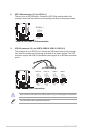
E45M1-M PRO
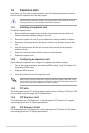
E45M1-M PRO Front panel audio connector
AAFP
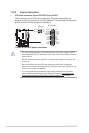
PIN 1
GND
PRESENCE#
SENSE1_RETUR
SENSE2_RETUR
PORT1 L
PORT1 R
PORT2 R
SENSE_SEND
PORT2 L
HD-audio-compliant
pin definition
PIN 1
AGND
NC
NC
NC
MIC2
MICPWR
Line out_R
NC
Line out_L
Legacy AC’97
compliant definition