


ASUS P5K/EPU
4-19
• Setting the CPU PLL Voltage, FSB Termination Voltage, DRAM Voltage
and North Bridge Voltage to a high level may damage the chipset, memory
module, and CPU permanently. Proceed with caution.
• Some values of the CPU PLL Voltage, FSB Termination Voltage, DRAM
Voltage and North Bridge Voltage items are labeled in different color,
indicating the risk levels of high voltage settings. Refer to the table below
for details.
• The system may need better cooling system to work stably under high
voltage settings.
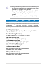
Blue Yellow Purple Red
CPU PLL Voltage 1.50V~1.78V 1.80V~2.00V 2.02V~2.20V 2.22V~2.78V
FSB Termination Voltage 1.20V~1.38V 1.40V~1.50V N/A N/A
DRAM Voltage 1.80V~1.98V 2.00V~2.20V 2.22V~2.40V 2.42V~3.08V
North Bridge Voltage 1.25V~1.41V 1.43V~1.55V 1.57V~1.73V 1.75V~1.91V
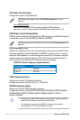
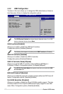
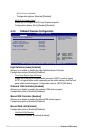
South Bridge Voltage [Auto]
Allows you to select the south bridge voltage. The values range from 1.05V to
1.20V with a 0.15V interval.
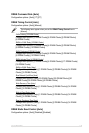
Clock Over-Charging Mode [Auto]
The values range from 0.70V to 1.00V with a 0.10V interval.
Load-Line Calibration [Auto]
Conguration options: [Auto] [Disabled] [Enabled]
CPU Voltage Reference [Auto]
Conguration options: [Auto] [0.63x] [0.61x] [0.59x] [0.57x]
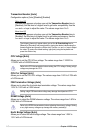
North Bridge Voltage Reference [Auto]
Conguration options: [Auto] [0.67x] [0.61x]
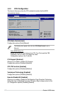
CPU Spread Spectrum [Auto]
Allows you to enable or disable the CPU spread spectrum.
Conguration options: [Auto] [Disabled]
PCIE Spread Spectrum [Auto]
Allows you to enable or disable the PCIE spread spectrum.
Conguration options: [Auto] [Disabled]