


8 ASUS T2 3-in-1 Upgrade User’s Guide
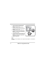
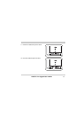
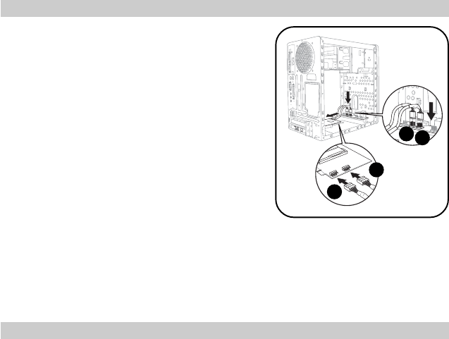
6. Connect one end of the first IEEE 1394 signal
cable to the IEEE 1394 connector labeled
IE1394_1 on the 3-in-1 card.
7. Connect one end of the second IEEE 1394
signal cable to the IEEE 1394 connector labeled
IE1394_2 on the 3-in-1 card.
8. Connect the other end of the first IEEE 1394
signal cable to the IEEE 1394 connector labeled
IE1394_1 on the front panel I/O daughterboard
of the Terminator 2 system.
9. Connect the other end of the second IEEE 1394
signal cable to the IEEE 1394 connector labeled
IE1394_2 on the front panel I/O daughterboard
of the Terminator 2 system.
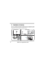
10. Replace the system cover.
7
6
9
8
NOTE:
For details on PCI card installation, refer to “Chapter 2: Basic Installation” of the Terminator 2
User Guide.