


ASUS F2A55-M
1-27
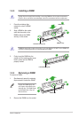
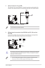
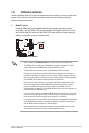
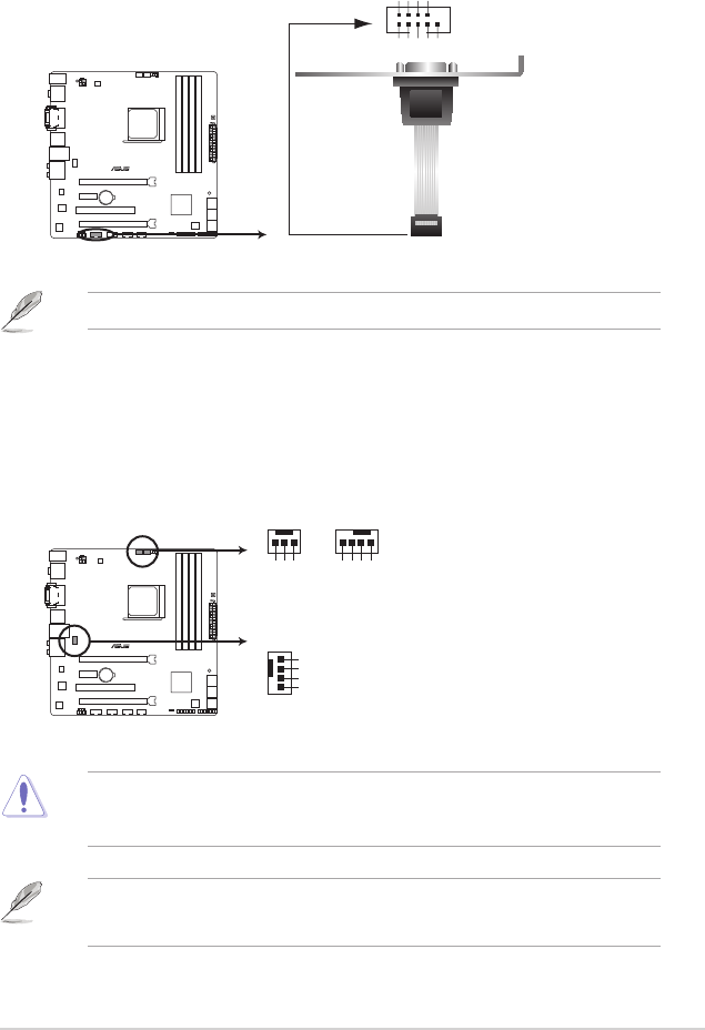
The COM module is purchased separately.
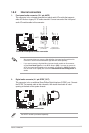
5. Serial port connector (10-1 pin COM)
This connector is for a serial (COM) port. Connect the serial port module cable to this
connector, then install the module to a slot opening at the back of the system chassis.
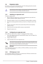
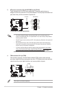
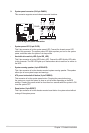
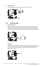
Do not forget to connect the fan cables to the fan connectors. Insufcient air ow inside the
system may damage the motherboard components. These are not jumpers! Do not place
jumper caps on the fan connectors!
• The CPU_FAN connector supports a CPU fan of maximum 2A (24 W) fan power.
• Only the 4-pin CPU fan & CHA fan support ASUS FanXpert feature.
F2A55-M
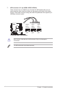
F2A55-M Serial port (COM) connector
PIN 1
COM
DCD
TXD
GND
RTS
RI
RXD
DTR
DSR
CTS
F2A55-M
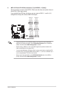
F2A55-M Fan connectors
CPU_FANPWR_FAN
CPU FAN PWM
CPU FAN IN
CPU FAN PWR
GND
CHA_FAN
GND
CHA FAN PWR
CHA FAN IN
CHA FAN DC mode
Rotation
+12V
GND
6. CPU and chassis fan connectors (3-pin PWR FAN, 4-pin CPU_FAN, and 4-pin
CHA_FAN)
Connect the fan cables to the fan connectors on the motherboard, ensuring that the
black wire of each cable matches the ground pin of the connector.