


1-26 Chapter 1: Product introduction
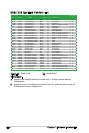
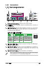
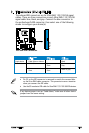
Audio 2, 4, or 6-channel configuration
Light Blue Line In Rear Speaker Out Rear Speaker Out
Lime Line Out Front Speaker Out Front Speaker Out
Pink Mic In Mic In Bass/Center
Port Headset 4-channel 6-channel
2-channel
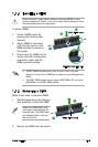
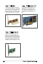
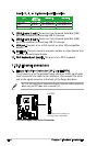
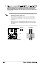
7. USB 2.0 ports 1 and 2. These two 4-pin Universal Serial Bus (USB)
ports are available for connecting USB 2.0 devices.
8. USB 2.0 ports 3 and 4. These two 4-pin Universal Serial Bus (USB)
ports are available for connecting USB 2.0 devices.
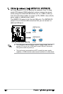
9. VGA port. This port is for a VGA monitor or other VGA-compatible
devices.
10. Serial port. This port connects a mouse, modem, or other devices that
conform with serial specication.
11. PS/2 keyboard port (purple). This port is for a PS/2 keyboard.
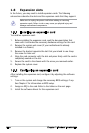
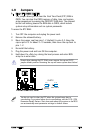
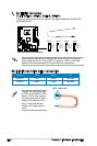
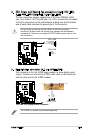
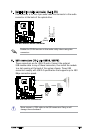
1.10.2 Internal connectors
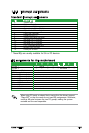
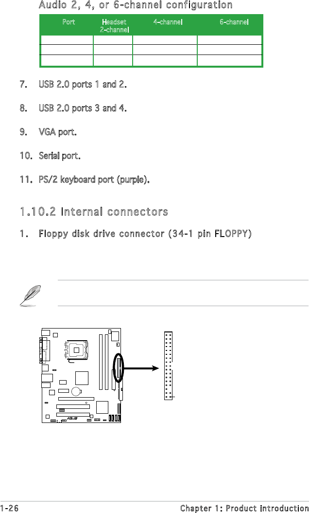
1. Floppy disk drive connector (34-1 pin FLOPPY)
This connector is for the provided oppy disk drive (FDD) signal cable.
Insert one end of the cable to this connector, then connect the other
end to the signal connector at the back of the oppy disk drive.
Pin 5 on the connector is removed to prevent incorrect cable connection
when using an FDD cable with a covered Pin 5.
P5L-MX
R
P5L-MX Floppy Disk Drive Connector
NOTE:
Orient the red markings o
n
the floppy ribbon cable to PIN 1.
PIN 1
FLOPPY