


ASUS P2L97-S User’s Manual 11
III. INSTALLATION
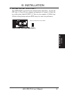
Jumpers
1) SCSI p. 13 Onboard SCSI Setting
2) FS0, FS1, FS2 p. 14 CPU Bus Frequency
3) BF0, BF1, BF2, BF3 p. 14 CPU Core:Bus Frequency Multiple
4) CLRTC p. 15 Clear Real Time Clock (RTC) RAM
Expansion Slots/Sockets
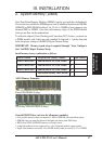
1) System Memory p. 17 System Memory Support
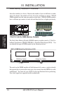
2) DIMM Sockets p. 18 DIMM Memory Module Support
3) SEC CPU Slot p. 19 Single Edge Contact CPU Support
4) SLOT1, SLOT2 p. 24 16-bit ISA Bus Expansion Slots
*
5) PCI1, PCI2, PCI3, PCI4 p. 25 32-bit PCI Bus Expansion Slots
†
6) AGP p. 25 Accelerated Graphics Port
Hardware Monitor
1) R_CPU p. 22 Pentium II Processor Thermal Sensor Connector
Connectors
1) PS2KEYBOARD p. 26 PS/2 Keyboard Connector (6-pin female)
2) PS2MOUSE p. 26 PS/2 Mouse Connector (6-pin female)
3) PRINTER p. 27 Parallel (Printer) Port Connector (25-pin female)
4) COM1, COM2 p. 27 Serial Port COM1 & COM2 (two 9-pin male)
5) FLOPPY p. 27 Floppy Drive Connector (34-1 pin block)
6) USB p. 28 Universal Serial BUS Ports 1 & 2 (two 4-pin female)
7) Primary / Second IDE p. 28 Primary / Secondary IDE Connector (40-pin blocks)
8) HDLED p. 29 IDE LED Activity Light (2 pins)
9) CHA_, CPU_, PWR_FAN p. 29 Chassis, CPU, Power Supply Fan Connectors (3-pin block)
10) IR p. 30 Infrared Port Module Connector (5 pins)
11) ATXPWR p. 30 ATX Motherboard Power Connector (20-pin block)
12) WOL p. 31 Wake on LAN (3 pins) (Reserved)
13) NARROW/WIDE SCSI p. 31 50-pin Fast SCSI II & 68-pin Fast&Wide SCSI III
14) TB_LED (PANEL) p. 32 LED Lead (2 pins)
15) SMI (PANEL) p. 32 SMI Switch Switch Lead (2 pins)
16) PWR_SW (PANEL) p. 32 ATX Power Switch / Soft Power Switch (2 pins)
17) RESET (PANEL) p. 32 Reset Switch Lead (2 pins)
18)
KEYLOCK (
PANEL
)
p. 32 System Power LED (3 pins)
19)
KEYLOCK (
PANEL
)
p. 32 Keyboard Lock Switch Lead (2 pins)
20) SPEAKER (PANEL) p. 32 Speaker Connector (4 pins)
*
The onboard hardware monitor uses the address 290H-297H so legacy ISA cards must not
use this address or else conflicts will occur.
†
PCI slots 4 share the same interrupt number (INT#) as the onboard SCSI so PCI slot 4 card
must be able to share an INT# or make sure that it does not use an INT# at all.
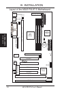
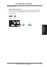
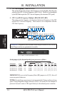
(Board Layout)
III. INSTALLATION