


1-6
Chapter 1: Product introduction
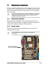
1.4 Motherboard overview
Before you install the P4B533 motherboard, familiarize yourself with its
physical configuration and available features to facilitate the motherboard
installation and future upgrades. A sufficient knowledge of the motherboard
specifications will also help you avoid mistakes that may damage the
board and its components.
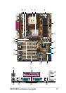
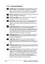
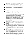
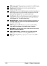
1.4.1 Major components
The following are the major components of the P4B533 motherboard as
pointed out in the picture on page 1-7.
1. ASUS EZ Plug™ +12V connector
2. ATX 12V connector
3. DIP switches (DSW1)
4. CPU socket
5. North Bridge controller
6. DDR DIMM sockets
7. Floppy connector
8. ATX power connector
9. South Bridge controller
10. IDE connectors
11. DIP switches (DSW2)
12. Flash EEPROM
13. ASUS ASIC
14. Standby power LED
15. Audio controller (optional)
16. PCI slots
17. Super I/O controller
18 AGP warning LED
19. AGP slot
20. PS/2 mouse port
21. Parallel port
22. Line In jack (optional)
23. Line Out jack (optional)
24. Microphone jack (optional)
25. USB 2.0 ports 1 and 2
26. Serial ports
27. USB 2.0 ports 3 and 4
28. Keyboard port
See page 1-8 for the specifications of each component. Refer to
Chapter 2 for detailed information on the components.