


ASUS P4P800-X motherboard
1-25
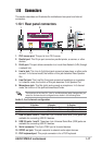
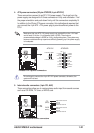
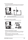
13. System panel connector (10-1 pin PANEL)
This connector accommodates several system front panel functions.
P4P800-X
R
P4P800-X System panel connector
PANEL
* Requires an ATX power supply.
PLED
PWRBIN
+5 V
+5V
Speaker
Speaker
Connector
Power LED
Ground
Reset SW
Ground
Reset
Ground
Ground
ATX Power
Switch*
HD_LED-
HD_LED+
IDELED
• System Power LED Lead (Green 3-1 pin PLED)
This 3-1 pin connector connects to the system power LED. The LED lights up
when you turn on the system power, and blinks when the system is in sleep
mode.
• System Warning Speaker Lead (Orange 4-pin SPKR)
This 4-pin connector connects to the case-mounted speaker and allows you to
hear system beeps and warnings.
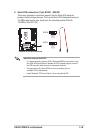
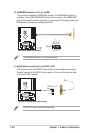
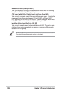
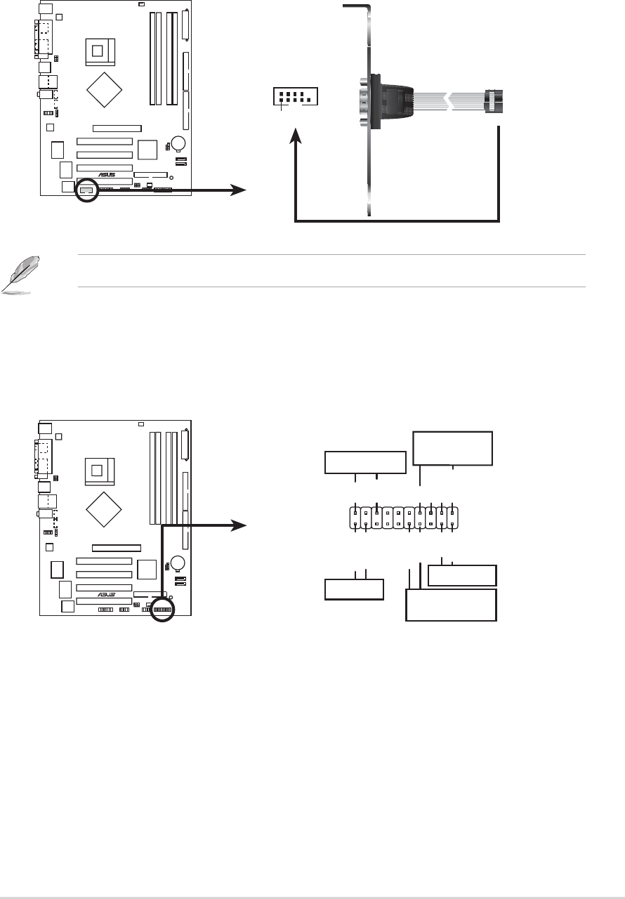
12. Serial connector (9-pin COM2 )
This 9-pin connector connects to a COM2 bracket. Connect the COM2 cable to
this connector and install the bracket on an available slot in the rear panel of
the chassis.
The COM2 bracket is purchased separately.
P4P800-X
®
P4P800-X Serial port connector
PIN 1
COM2