1-16
Chapter 1: Product introduction
1.12 Connectors
This section describes and illustrates the internal connectors on the motherboard.
P4PE-X/TE
®
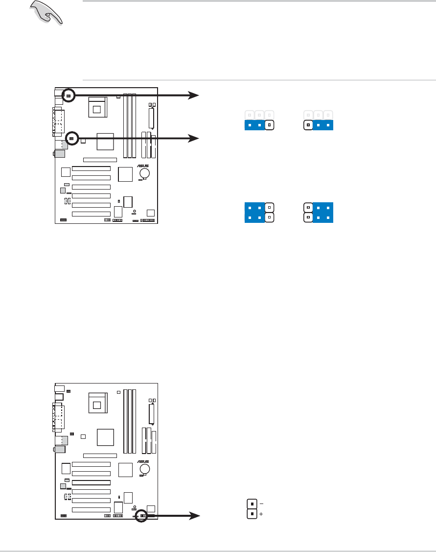
P4PE-X/TE HD Activity LED
TIP: If the case-mounted LED does no
t
light up, try reversing the 2-pin plug.
IDE_LED1
1. Hard disk activity LED (2-pin IDE_LED1)
This connector supplies power to the hard disk activity LED. The read or write
activities of any device connected to the primary or secondary IDE connector
cause this LED to light up.
3. USB device wake-up (3-pin USBPW12, USBPW34, USBPW56)
Set these jumpers to +5V to wake up the computer from S1 sleep mode (CPU
stopped, DRAM refreshed, system running in low power mode) using the
connected USB devices. Set to +5VSB to wake up from S3 sleep mode (no
power to CPU, DRAM in slow refresh, power supply in reduced power mode).
Both jumpers are set to pins 1-2 (+5V) by default because not all computers
have the appropriate power supply to support this feature.
The USBPW12 and USBPW34 jumpers are for the rear USB ports. The
USBPW56 jumper is for the internal USB header that you can connect to the
front USB ports.
1. This feature requires a power supply that can provide at least 1A on the
+5VSB lead when these jumpers are set to +5VSB. Otherwise, the system
would not power up.
2. The total current consumed must NOT exceed the power supply capability
(+5VSB) whether under normal condition or in sleep mode.
P4PE-X/TE
®
P4PE-X/TE USB Device Wake Up
3
2
21
+5V
(Default)
+5VS
B
USBPW34
USBPW56
+5V
(Default)
+5VS
B
USBPW12
3
2
21


