


1-16
Chapter 1: Product introduction
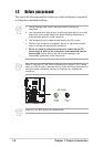
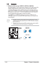
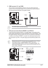
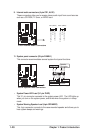
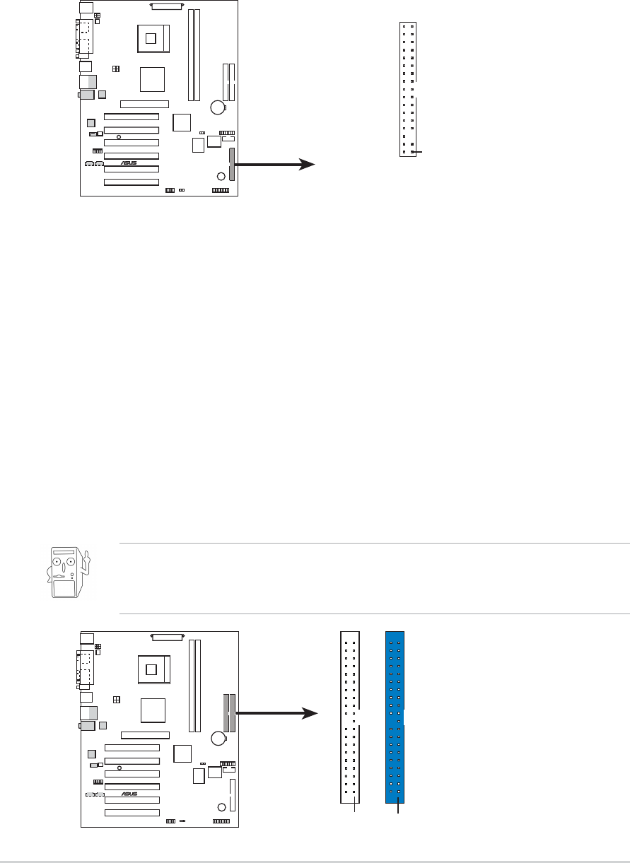
1. Floppy disk drive connector (34-1 pin FLOPPY1)
This connector supports the provided floppy drive ribbon cable. After
connecting one end to the motherboard, connect the other end to the floppy
drive. (Pin 5 is removed to prevent incorrect insertion when using ribbon cables
with pin 5 plug).
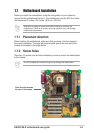
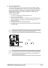
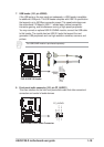
2. IDE connectors (40-1 pin PRI_IDE1, SEC_IDE1)
This connector supports the provided UltraDMA133/100/66 IDE hard disk ribbon
cable. Connect the cable’s blue connector to the primary (recommended) or
secondary IDE connector, then connect the gray connector to the
UltraDMA133/100/66 slave device (hard disk drive) and the black connector to
the UltraDMA133/100/66 master device. It is recommended that you connect
non-UltraDMA133/100/66 devices to the secondary IDE connector. If you install
two hard disks, you must configure the second drive as a slave device by setting
its jumper accordingly. Refer to the hard disk documentation for the jumper
settings. BIOS supports specific device bootup. If you have more than two
UltraDMA133/100/66 devices, purchase another UltraDMA133/100/66 cable.
You may configure two hard disks to be both master devices with two ribbon
cables – one for the primary IDE connector and another for the secondary IDE
connector.
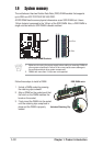
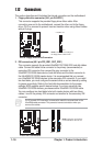
1.12 Connectors
This section describes and illustrates the internal connectors on the motherboard.
P4S-X
®
NOTE: Orient the red markings o
n
the floppy ribbon cable to PIN 1.
P4S-X Floppy Disk Drive Connector
PIN 1
FLOPPY1
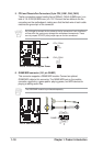
P4S-X
®
P4S-X IDE Connectors
NOTE: Orient the red marking
s
on the IDE ribbon cable to
PIN
1
SEC_IDE1
PIN 1
PRI_IDE1
PIN 1
Pin 20 on each IDE connector is removed to match the covered hole on the
UltraDMA cable connector. This prevents incorrect orientation when you
connect the cables.