


16
ASUS P4T-M Quick Setup Manual
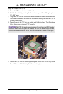
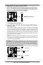
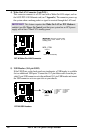
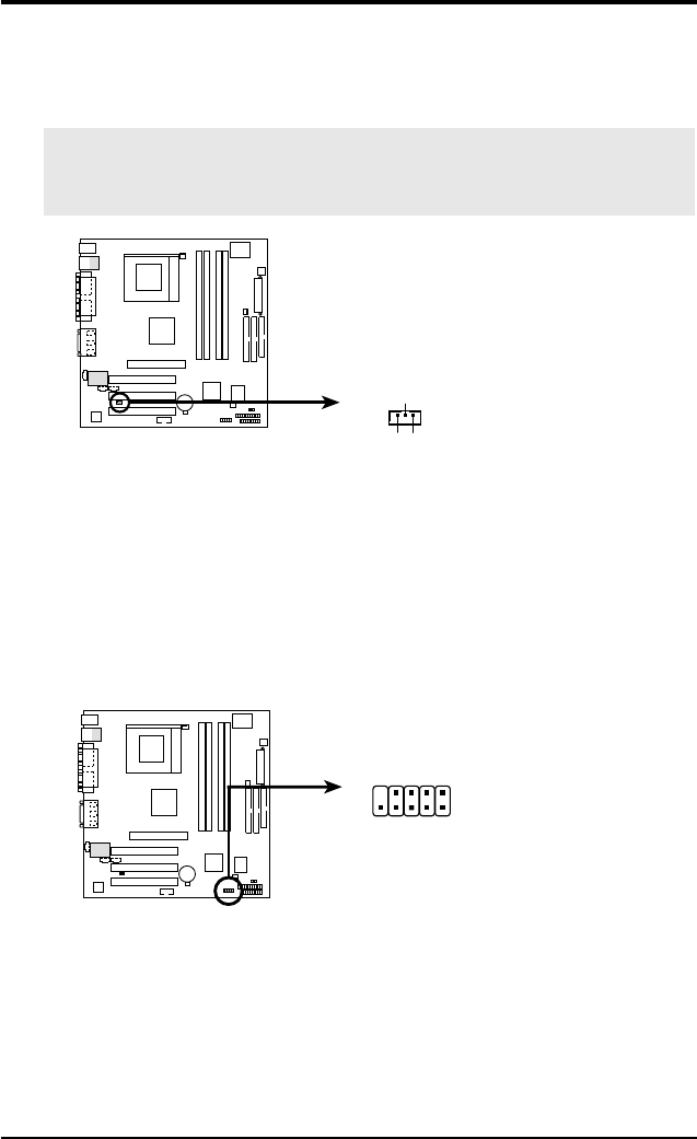
5) USB Headers (10-1 pin USB2)
If the USB Ports on the back panels are inadequate, a USB header is available
for two additional USB ports. Connect the 10-1 pin ribbon cable from the pro-
vided 2-port USB connector set to the midboard 10-1 pin USB header and mount
the USB connector set to an open slot on your chassis.
P4T-M
P4T-M USB Headers
USB2
15
610
1: USB Power
2: USBP2–
3: USBP2+
4: GND
5: NC
6: USB Power
7: USBP3–
8: USBP3+
9: GND
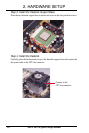
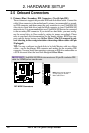
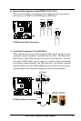
4) Wake-On-LAN Connector (3-pin WOL)
This connector connects to a LAN card with a Wake-On-LAN output, such as
the ASUS PCI-L101 Ethernet card (see 7. Appendix). The connector powers up
the system when a wakeup packet or signal is received through the LAN card.
IMPORTANT: This feature requires that Wake On LAN or PCI Modem is
enabled (see 4.5.1 Power Up Control) and that your system has an ATX power
supply with at least 720mA +5V standby power.
P4T-M
P4T-M Wake-On-LAN Connector
IMPORTANT: Requires an ATX power
supply with at least 720mA +5 volt
standby power
+5 Volt Standby
PME
Ground
WOL_CON