


30 ASUS P5A User’s Manual
III. INSTALLATION
Connectors
III. INSTALLATION
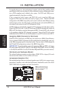
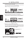
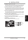
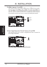
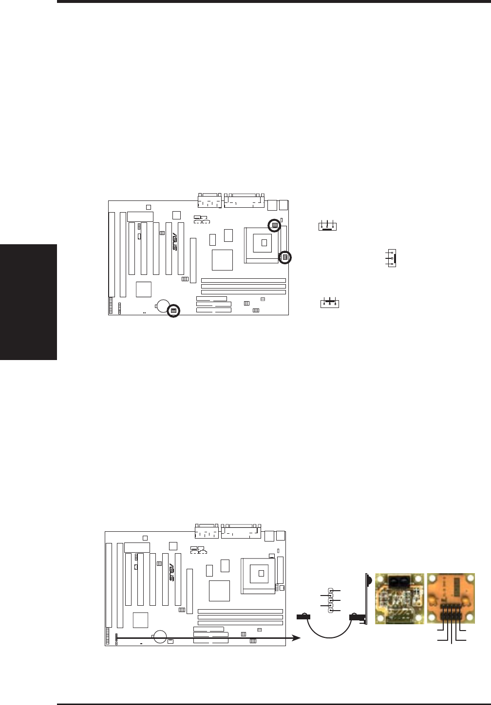
13. CPU Cooling Fan Connectors (FAN, 3 pins)
This connector supports a 3-pin CPU cooling fan of 500mA (6W) or less with a
minimum of 3,500RPM. Depending on the fan manufacturer, the wiring and
plug may be different. The red wire should be Positive, the black should be
Ground, and the yellow wire should be Rotation signal.
WARNING! The CPU and/or motherboard will overheat if there is no airflow
across the CPU. Damage may occur to the motherboard and/or the CPU fan if
these pins are incorrectly used. These are not jumpers, do not place jumper
caps over these pins.
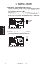
P5A 12Volt Cooling Fan Power
CPU Fan Power
GND
Rotation
+12V
GND
Rotation
+12V
R
GND
Rotation
+12V
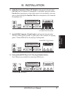
Chassis Fan Power
Power Supply Fan
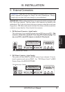
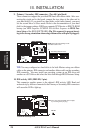
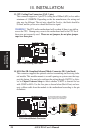
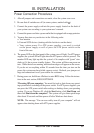
14. IrDA/Fast IR-Compliant Infrared Mdule Connector (IR, 5-pin block)
This connector supports the optional wireless transmitting and receiving infra-
red module. This module mounts to a small opening on system cases that sup-
port this feature. You must also configure the setting through UART2 Use Infra-
red in Chipset Features Setup to select whether UART2 is directed for use
with COM2 or IrDA. Use the five pins as shown below (Back View) and con-
nect a ribbon cable from the module to the motherboard according to the pin
definitions.
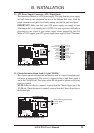
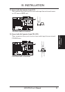
P5A Infrared Module Connector
For the infrared feature to be available,
you must connect an infrared (IrDA)
module (optional) to the motherboard
R
Front View
+5V
IRTX
IRRX
FIRRX
GND
Back View
IRRX
+5V
IRTX
FIRRX
GND