


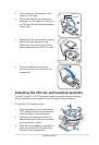
3
Installation manual
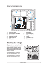
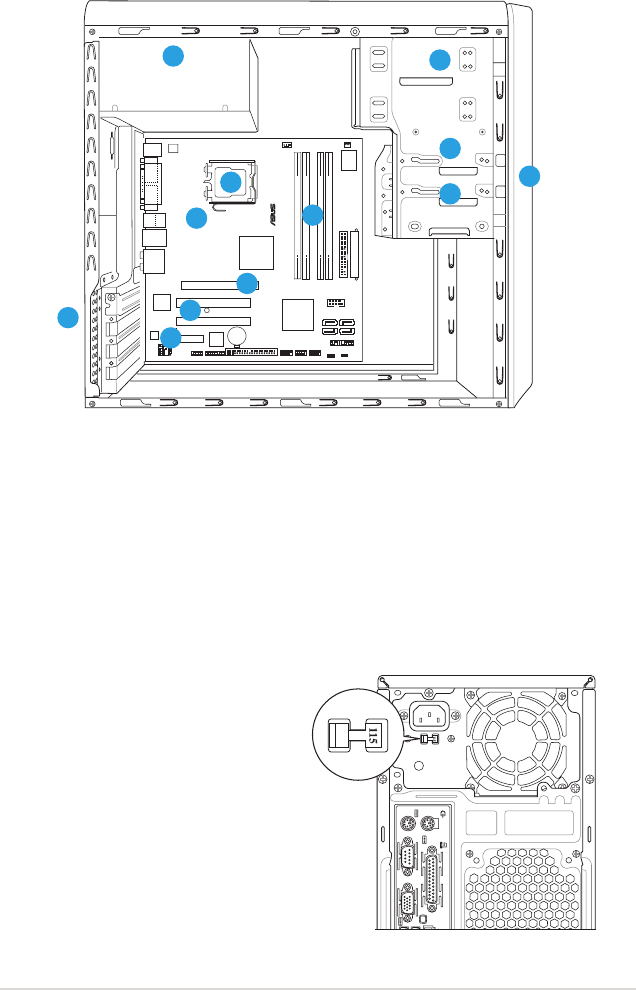
Selecting the voltage
The system’s power supply unit has a 115
V/230 V voltage selector switch located
beside the power connector. Use this
switch to select the appropriate system
input voltage according to the voltage
supply in your area.
If the voltage supply in your area is
100-127 V, set the switch to 115 V.
If the voltage supply in your area is
200-240 V, set the switch to 230 V.
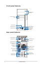
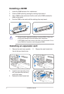
CR2032 3V
Lithium Cell
CMOS Power
CD
Super
I/O
A
TX12V
AAFP
DDR DIMM_A1 (64 bit,240-pin module)
SB_PWR
USB78
USB56
CLRTC
PCI1
Intel
®
GMCH
945G
Intel
®
ICH7
DDR DIMM_A2 (64 bit,240-pin module)
DDR DIMM_B1 (64 bit,240-pin module)
DDR DIMM_B2 (64 bit,240-pin module)
CHA_FAN
CPU_FAN
EATXPWR
PCI2
SPDIF_OUT
Intel
82573L
PS/2KBMS
T: Mouse
B: Keyboard
PCIEX1_1
PCIEX16
COM1
PARALLEL PORT
VGA
PANEL
®
SATA1 SATA2
SATA4SATA3
FLOPPY
PRI_IDE
COM2
ALC882
TI
TSB43AB22A
ADH
LGA775
LAN_USB34
AUDIO
USB1
USB2
Bottom:
1394
Top:
IE1394_2
USB910
CHASSIS
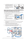
Internal components
1. Front panel cover
2. 5.25-inch optical drive bays
3. Hard disk drive bay
4. Floppy disk drive bay
5. Power supply unit
6. CPU socket
7. DIMM sockets
8. ASUS motherboard
9. PCI Express x16 slot
10. PCI slots
11. PCI Express x1 slot
12. Metal bracket lock
6
1
2
3
4
12
10
7
8
5
11
9